|
|||||||||||||||
|
|
|||||||||||||||
|
Feature Articles: Latest Development Trend at NTT Access Network Service Systems Laboratories Vol. 10, No. 6, pp. 1–7, June 2012. https://doi.org/10.53829/ntr201206fa1 Technology for Reconnecting Optical Fiber Cable in Existing Aerial ClosuresAbstractWe have developed a technology for connecting short remnant lengths of optical fiber that enables the reconnection of optical fiber cable in existing aerial drop closures, which is currently difficult because the remnant length is insufficient. 
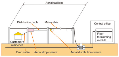
1. IntroductionThe number of broadband contracts in Japan reached 36 million in September 2011. Among those, the number of fiber-to-the-home (FTTH) contracts exceeded 21 million, which is more than half the total number of all broadband service contracts (59%) [1]. Accompanying these trends, there have been changes to other services because of service diversification and because of service transfer or termination when customers move home and so forth. For the convenience of new residents and for efficient connection work when services are transferred or cancelled, some of the cabling facilities are left in place, but this has the drawback of lowering the utilization rate of existing facilities. To counter this problem and make more efficient use of existing facilities, we have developed an optical fiber cable reconnection technology that enables the reconnection of optical fibers remaining in aerial drop closures [2] after an optical fiber drop connection has been cut. 2. ConceptTo enable optical services to be offered to customers at their residences, aerial distribution closures are commonly used. Each one is fitted off-site in advance with an optical splitter of appropriate capacity. When service is newly provided to a customer, an optical fiber cable (drop cable) is fed to the customer’s residence from an aerial optical drop closure, which is connected to the aerial distribution closure via a distribution cable (Fig. 1).
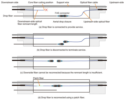
The aerial drop closure at a customer’s residence is often an AOF or AOF24 closure (Fig. 2). These closures are compact and economical facilities that can be installed as demand arises. However, in order to improve their drop cabling workability, optical core fibers pass through the aerial drop closure in straight lengths. When a drop cable is installed and connected to the upstream-side (central-office side) cable via an FAS (field assembly small-sized) connector, the optical fiber cable in the closure is cut, an FAS connector socket is attached to the upstream-side fiber and connected to the FAS connector plug of the drop cable, and a short remnant length of the downstream-side optical fiber is left inside the closure. However, once the optical fiber has been cut, reconnection of the upstream and downstream optical fibers has, until now, been difficult owing to the short length of downstream-side optical fiber remaining in the closure. This is because, when an FAS connector is installed, some of the upstream-side cable is lost since the fiber must be trimmed with a fiber cutter. With the straight-fiber configuration, reconnection of the upstream- and downstream-side fibers is impossible using this shortened length of core fiber, as shown in Fig. 2(c): even after a connector has been attached, the optical fiber does not reach the connector (in the case of existing connectors). Reconnection is enabled (Fig. 2(d)) by a newly developed patch fiber, as explained in section 3.1.
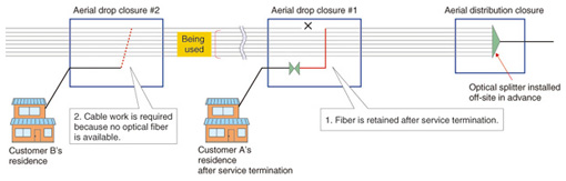
The problem is illustrated in Fig. 3. When service was supplied to Customer A, one of the eight fibers from the splitter in the aerial distribution closure was cut in drop closure #1 and a drop cable was installed. Later, customer A terminated the service contract, but the cut downstream fiber is not available to other customers. For example, consider the situation when Customer B further downstream requests service. Although seven of the fibers in drop closure #2 are in use, one fiber is not being used; however, it is not connected to the NTT central office because it was cut further upstream in drop closure #1. Until now, the only way to provide service to Customer B has been to lay additional cable, but new optical cabling work is expensive. It would be more efficient and economical if we could utilize the spare fiber in drop closure #2 by reconnecting the cut in drop closure #1. Considering this situation, we identified three needs: (1) a patch fiber that can easily be connected with the remnant lengths of downstream-side optical fibers in aerial drop closures, (2) connectors that can be attached in the empty space in an existing closure without compromising the closure’s functions, and (3) fiber protection during the additional stripping of existing cables because workability is especially poor with the shorter remnant lengths of downstream-side optical fibers in AOF closures.
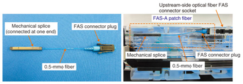
To meet these needs, we have developed an optical aerial closure patch fiber suitable for the 150-mm remnant length in an AOF24 closure and an extension sleeve to adapt it to work with the shorter 80-mm remnant length in an AOF closure. We also developed tools for connecting short remnant lengths and a tray for downstream-side cable reconnection. The patch fiber enables reconnection of the upstream and downstream fibers, the tray provides mechanical support during this reconnection procedure. 3. Development3.1 FAS-A patch fiberWe developed two types of patch fibers (called A and B) in order to reconnect an optical fiber (Fig. 4). The FAS-A (FAS type A) patch fiber (diameter: 0.5 mm) has an FAS connector plug at one end and a mechanical splice at the other end. The FAS connector plug is designed to mate with the FAS connector socket added to the upstream-side optical fiber in the closure when the optical fiber drop cable was installed. The mechanical splice is a two-sided joint which is connected to the patch fiber on one side and open the other side. The FAS-A patch cable is factory-assembled for maximum quality. To connect the FAS-A patch fiber to the downstream-side optical fiber, the field technician connects the mechanical splice to the downstream fiber. This requires only a short length of downstream fiber, which makes on-site work more efficient and reduces the number of connection failures and subsequent optical fiber shortening. Furthermore, by designing a short patch fiber, we can avoid the need to store rolled-up fiber and can instead store it straight; this minimizes the space required for storage and ensures good workability.
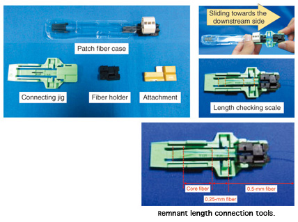
3.2 Connection toolsTo make a connection in the confined space in AOF and AOF24 closures, we have developed short remnant fiber length connection tools that can connect the short lengths available by moving the patch fiber with the attached mechanical splice toward the fixed remnant length of the downstream-side optical fiber (Fig. 5). The patch fiber is stored in a patch fiber case, and the V-shaped mechanical splice connection is set up in advance. The connection is made simply by pulling the patch fiber out of the case and into the connecting jig, onto which are mounted a fiber holder and an attachment. The improved workability means that a field technician can insert the optical fiber into the mechanical splice with one hand.
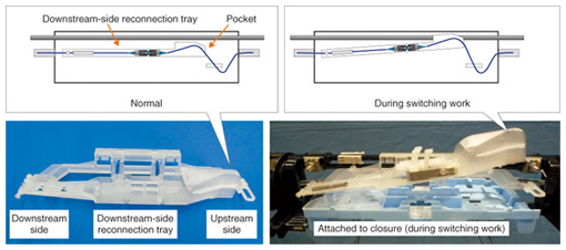
To ensure good workability with the short remnant lengths of optical fiber, we have made the fiber holder as small as possible. We designed the connection procedure in a failsafe manner to ensure that the technician does not perform the procedure incorrectly. We slanted the bottom of the fiber holder so that the technician will feel uncomfortable if he or she does not use the attachment when stripping the sheath or when cutting the fiber. The jig has a length checking scale marked on it so that the technician can ensure that the fiber is the appropriate length without requiring a ruler. 3.3 Downstream-side reconnection trayThe downstream-side reconnection tray is designed to hold the patch fiber and to fit into the empty space inside the AOF or AOF24 closure (Fig. 6). We have ensured workability by storing the optical fiber straight (rather than in a loop), holding the patch fiber connection, and including a pocket to store the extra length of the upstream-side optical fiber. Moreover, the tray structure allows for free positioning and attachment of the upstream FAS connector and downstream mechanical splice connection. As well as those innovations, we have designed the tray to move up or down by means of a pivot at the mechanical-splice side so that it does not impede reconnection work in the AOF or AOF24 closure or work during the switching of the upstream-side optical fibers.
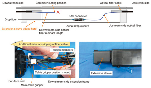
3.4 Extension sleeve and extension frame for downstream-side extensionWith the AOF closure, the remnant length of downstream-side optical fiber is shorter than in the AOF24 closure (80 mm versus 150 mm). In this case, an additional length of the downstream-side optical fiber cable must be pulled into the closure and stripped back until the exposed fiber length is 150 mm, the same as in the case of the AOF24 closure (Fig. 7). The procedure is as follows: (1) Slide the AOF closure end-face seal attached to the drop fiber cable downwards. (2) Remove the gripper from the existing main cable, attach the downstream-side extension frame to the closure frame, and then secure the cable with the cable gripper. (3) Pull the tension members apart by hand to strip the sheath from the cable (no tools required). (4) Cut the optical fiber cable sheath and partition. (5) Using binders (not shown in Fig. 7), secure the optical fiber cable sheath in order to fix its position. (6) To ensure drip-proofing along the section of additional stripping, attach the extension sleeve when the AOF closure end-face seal is moved. We have made the system more economical by making the AOF closure end-face seal reusable.
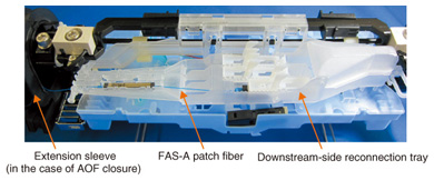
4. ConclusionBy enabling the reconnection of optical fiber cables in existing AOF and AOF24 closures (Fig. 8), these developments promise efficient use of existing aerial optical cables and will contribute to facility construction and lower operating costs. These short remnant-length optical fiber connection technologies also hold future promise for use in a wide range of other tight-space applications.
References
|
|||||||||||||||