|
|||
|
|
|||
|
Feature Articles on Technical Solutions to Real-world Problems Vol. 10, No. 7, pp. 10–14, July 2012. https://doi.org/10.53829/ntr201207fa2 Case Studies of Faults and Countermeasures in a Passive Optical Network SystemAbstractThis article reports faults unique to an optical access system based on passive optical networks (PONs). It presents (1) communication trouble caused by abnormal signal light emission from an uncontrolled optical network unit (ONU) and (2) facility trouble involving fatal damage to an optical fiber end surface of the connector used for video delivery services over a transmission line. It also describes appropriate countermeasures for these faults. 
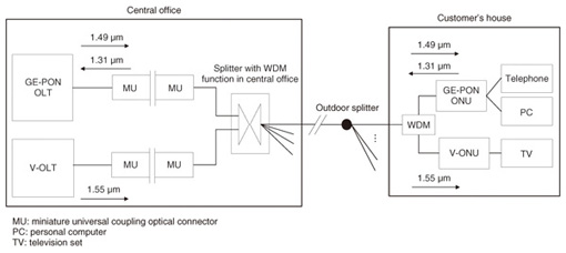
1. IntroductionThe demand for three kinds of service (Internet service, Internet telephone service, and video delivery service) is growing and the number of network facilities is increasing rapidly as the penetration of optical broadband services accelerates. NTT supplies these services, which are called FLET’S HIKARI, to customers via passive optical networks (PONs). A typical configuration of access network facilities from the central office to a customer’s house is shown in Fig. 1.
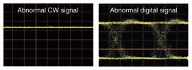
Today’s optical access facilities provide ultrahigh-speed communication services and video delivery services to multiple customers over one optical fiber. Gigabit Ethernet PON (GE-PON) is a technology that provides ultrahigh-speed communications at 1 Gbit/s in the access segment. The GE-PON is capable of communicating using the Internet protocol (IP) data method. A GE-PON optical line terminal (GE-PON OLT) in the central office provides Internet connection services and IP telephone services through IP data communications to the GE-PON optical network unit (GE-PON ONU) in the customer’s house. The GE-PON communication uses two wavelengths: 1.49 µm and 1.31 µm in the downstream and upstream directions, respectively. In addition, a visual-OLT (V-OLT) transmits video delivery services (called FLET’S TV by NTT) using the 1.55-μm wavelength band in the downstream direction. Optical signals from both the GE-PON OLT and the V-OLT are multiplexed in a splitter that has a function for wavelength division multiplexing (WDM) and delivered to customers via a single optical fiber and those signals are demultiplexed with a wavelength-division demultiplexer (labeled WDM in Fig. 1) in the customer’s house. 2. Case studies2.1 Case 1: Fault caused by abnormal light-wave emission from uncontrolled ONU2.1.1 Fault descriptionThere was an unique fault in the GE-PON system, which was reported at the same time by a number of customers. The NTT fault reception department checked facility information and alarm conditions on the operations system and discovered “upstream-error-rate deterioration” and “service immobilization” alarms for multiple ONUs. During troubleshooting, it was found that disconnecting a certain ONU from the system (such as by turning off its power or unplugging its optical cord) would restore the other ONUs where faults had occurred. 2.1.2 Cause of faultAn investigation of this disconnected ONU revealed that when power was applied to it, it generated a steady output of a continuous wave (CW) signal at a wavelength of 1.31 μm with a power level of +2 dBm. It was inferred that this CW signal affected the other ONUs administered by the same PON OLT interface package. In another similar fault case, we also discovered abnormal optical digital signal emission from an uncontrolled ONU, which incessantly output a 1.31-µm optical digital signal. Examples of the waveforms of the abnormal CW signal and the abnormal digital signal of faulty ONUs are shown in Fig. 2.
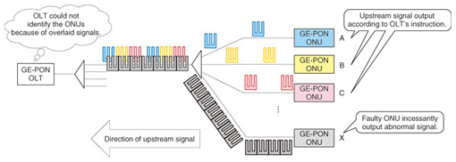
The cause of this particular fault can be explained as follows. Ignoring OLT control because of faulty operation, the faulty ONU output a continuous upstream signal (CW signal) that was overlaid on the upstream signals from other ONUs allocated by the same PON-OLT interface package (Fig. 3). This prevented the OLT from identifying all of the ONUs and resulted in the generation of upstream-error-rate-deterioration and service-immobilization alarms.
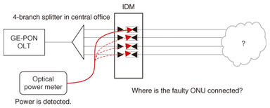
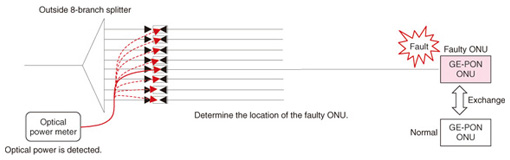
2.1.3 CountermeasureThe generation of upstream-error-rate-deterioration and service-immobilization alarms in multiple ONUs allocated by the same PON-OLT interface package suggested that the fault might have been caused by an ONU with abnormal light-wave emission. In this case, simply arranging to exchange the ONUs reported to be experiencing problems would not have resulted in their restoration and might only have prolonged the situation. To troubleshoot such a problem as quickly as possible, one must begin troubleshooting at the OLT-side 4-branch splitter in the central office. Specifically, the optical fiber connectors for the four paths at the integrated distribution module (IDM) must be physically disconnected in turn, power from the connector must be detected using a power meter, and the connector where the faulty ONU is connected must be identified (Fig. 4).
Under these circumstances, a normally operating ONU cannot launch signal light if it is disconnected from the OLT. The absence of received optical power here would therefore indicate normal ONU operation. By contrast, the presence of received optical power would indicate that the faulty ONU with abnormal signal light is connected to the optical fiber connector. Next, on the OLT-side of the outside 8-branch splitter, one must disconnect the eight optical fiber connectors in turn and identify as described above and check each connector for received optical power from that ONU using an optical power meter. Finally, once the faulty ONU has been located, it can be exchanged with a normal one to complete the repair procedure (Fig. 5).
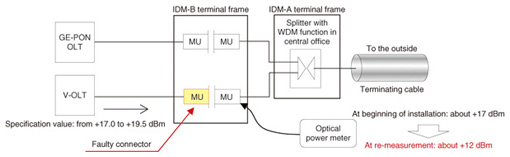
Before an optical fiber connector at the IDM or outside 8-branch splitter is reconnected, its optical connector plug or adaptor must be cleaned. 2.2 Case 2: Fatal damage to optical fiber end surface of the connector2.2.1 Fault descriptionThis case study involved a miniature universal coupling (MU) connector on an IDM-B used for video delivery services (FLET’S TV). At the beginning of installation of intra-office equipment (V-OLT), the received power level at the MU connector was found to be +17 dBm. After a while, when it was re-measured upon connection. it was found to be +12 dBm. The insertion loss at the MU connector increased to about 5 dB. The facility configuration in which this fault occurred is shown in Fig. 6. The insertion loss did not improve even after the optical fiber end surface of the MU connector had been carefully cleaned, so an investigation into the cause of the fault was conducted.
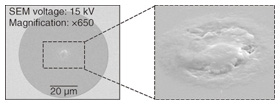
2.2.2 Cause of faultThe investigation began with optical characteristics. The return loss at the end of the faulty connector in air was found to be abnormal at about 39 dB compared with about 14 dB for a normal connector; moreover, the loss when connected was also large at about 5 dB, as mentioned above. Next, the connector was dismantled and the connector ferrule end surface was inspected using a scanning electron microscope (SEM). This revealed signs of fatal damage caused by silica-melting in the core section (Fig. 7).
An experiment was conducted to reproduce the fault: light from the V-OLT was injected into the connector and the tip of the MU connector was exposed to various types of contamination from oily hands, clothes (work shirts), dust, etc. It was found that fatal damage caused by silica-melting occurred in the core section and that the loss increased in the case of all of these types of contamination, but that the signs of damage observed for contamination by oily hands and clothes most closely resembled the characteristics seen in this case study. It was therefore inferred that the high optical power of the V-OLT equipment was converted into heat by the contamination on the optical fiber end surface of the connector and that this led to the silica-melting in the core section. 2.2.3 CountermeasureIt is important to eliminate contamination from a connector end surface by using a cleaner. Specifically, it is essential to clean an optical connector plug and adaptor using specialized cleaners before connecting them (Fig. 8).
3. ConclusionThis article presented case studies of faults and countermeasures in a PON system. The Technical Assistance and Support Center, NTT EAST Corporation will continue in its efforts at technical consulting and fault analysis with the aim of maintaining a safe and secure network for its customers. |
|||