 |
|||||||||||||
|
|
|||||||||||||
|
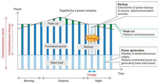
Feature Articles: Environmental and Energy Technologies for ICT Society Vol. 11, No. 1, pp. 17–22, Jan. 2013. https://doi.org/10.53829/ntr201301fa3 Secondary Batteries and Fuel Cells for Telecommunication Facilities with Improved Tolerance to Power OutagesAbstractThe long-lasting commercial power outage caused by the catastrophic earthquake in eastern Japan in 2011 demonstrated the importance of the power supply in providing continuous telecommunication services. This article introduces an approach to power supply to ensure that telecommunication services operate normally in all situations and describes the development of high energy density secondary batteries and highly efficient fuel cells to achieve energy storage and generation for that purpose. 1. IntroductionThe NTT Group uses about 1% of the total electrical power produced in Japan (8.9 trillion kWh per year) to provide telecommunication services, so reducing that figure is important from environmental and energy viewpoints. Furthermore, the damage to NTT’s telecommunication facilities caused by the Great East Japan Earthquake in March 2011 amounted to over 100 trillion yen [1]. The role of telecommunication services in the event of disasters such as earthquakes, floods, and typhoons is increasing in importance, and it is therefore necessary to ensure that services are provided continuously at all times. One requirement in achieving continuous service is to maintain the supply of power to telecommunication facilities. Many telecommunication facilities operate on commercial power and so are equipped with lead-acid batteries for a backup power supply in the event of power outages. However, the outages caused by the catastrophic earthquake in 2011 exceeded all possible backup times. Thus, service continuation in such circumstances requires a reduced dependence on commercial power and an extended backup time. Three strategies can be considered to address issues concerning the power supply to telecommunication facilities (Fig. 1). One is to extend the backup time to cope with power outages. Another is to implement a cut or shift in peak usage to deal with power supply shortages. The third strategy is to reduce the dependence on commercial power by generating power locally and to ensure that important installations receive a certain minimum amount of power. In order to give telecommunication facilities improved tolerance to power outages, NTT Energy and Environment Systems Laboratories has been conducting research and development (R&D) of secondary battery and fuel cell technologies for implementing these strategies.
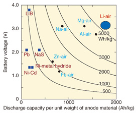
2. High-energy-density secondary batteries2.1 Trends in secondary battery R&DCoping with long-term power outages requires higher storage capacity in order to increase the backup time. For example, if backup time is extended from 3 hours to 24 hours, eight times as much storage is required. Current power supply backup systems mainly use lead-acid batteries. However, it is often not possible to provide the space needed for an eight-fold increase in the number of batteries. In other words, it is desirable to install batteries that have eight times the capacity (eight times the energy density) of lead-acid batteries in the same installation space. Currently, the leading high-energy-density batteries are the lithium-ion batteries (LIBs) that are used in notebook computers, cell phones, smartphones, and even electric vehicles (EVs). LIBs have been commercially available since 1991. However, current EVs are limited to a short driving range of about 100 km to 200 km on a single charge. To extend the range to 500 km per charge, next-generation batteries that have higher energy density (post-LIBs) are currently being developed. Extending telecommunication facility power backup to 24 hours also requires high- energy-density post-LIB battery technology. Post-LIBs include air batteries that use the oxygen in air. These batteries have been attracting attention for their potential use in achieving long-term electricity backup [2]. The calculated limiting energy densities for various air batteries are shown in Fig. 2, and that of LIB is indicated for comparison. Here, the limiting energy density is calculated under the assumption that the battery contains only the anode and cathode materials, which are directly related to the battery reaction. Of course, all actual batteries contain materials that are not directly related to the reaction, for example, electrolytes, separators, and current collectors. Thus, the limiting energy density is not available in practice; the effective capacity of real batteries is only about 25–50% of that value.
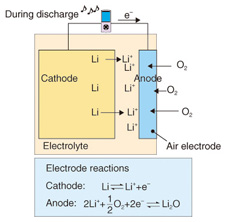
As we can see in Fig. 2, each of the air batteries has a higher limiting energy density than the LIB. This is because air batteries obtain the anode material, which is oxygen, from the air, so the entire battery consists only of the cathode material. Accordingly, the usable capacity is near the limiting energy density. In particular, the lithium-air battery has the highest limiting energy density, over ten times that of the LIB. 2.2 Lithium-air batteriesWhen a lithium-air battery is discharging (Fig. 3), oxygen is taken from the air at the anode, which is also called the air electrode. At the same time, lithium ions from the lithium cathode dissolve into the electrolyte at the cathode. The lithium ions from the electrolyte react with oxygen at the anode to form lithium oxide. The reverse reaction occurs when the battery is charging. This operation is expressed by the following chemical reactions.
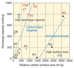
Anode reaction: (x/2)O2+ Li++ e- ⇔ LiOx Cathode reaction: Li ⇔ Li++ e- Overall battery reaction: (x/2)O2+ Li → LiOx Lithium can be used for the cathode of a lithium-air battery, and the same technology for lithium ion batteries can most likely be applied for the electrolyte, separator, etc. Therefore, the key factors for implementing rechargeable air batteries are the air electrode and the technologies related to it. The discharge characteristics of the various forms of carbon materials used in the development of the air electrode have been studied and compared. The relationship of capacity to relative surface area and unit weight for various carbon materials (Fig. 4) shows that the capacity tends to increase with the relative surface areas of the different forms of carbon; it increases in the order: carbon black, graphite, and activated charcoal. Among those, K6 (a form of carbon black) has the highest capacity.
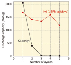
Although K6 features high capacity, the capacity decreases to almost zero after charging and discharging (i.e., one charge/discharge cycle) about three times (Fig. 5). That effect is believed to result from educed lithium compounds on the carbon remaining on the electrode without being decomposed.
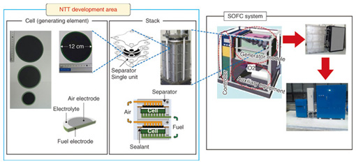
Therefore, catalysts for promoting the decomposition of the chemical products of cell discharge and thus, for retaining greater capacity over more charge/discharge cycles have been studied [3]. The result of that work led to the use of the oxide La0.6Sr0.4Fe0.6 Mn0.4O3 as an additive to the anode carbon. Although this additive reduced the original capacity by about 20%, that capacity was retained over repeated charge/discharge cycles. In the future, we will aim for even higher capacity and good charge/discharge cycle characteristics in order to achieve practical lithium-air batteries. 3. Fuel cells3.1 Trends in fuel cell technology and R&DFuel cells generate electrical power cleanly and with high efficiency by extracting electrical energy from the process of forming water from hydrogen and oxygen. Fuel cell co-generation systems for home use have been sold under the name Ene-Farm since 2009. In the beginning, only polymer electrolyte fuel cells (PEFCs) were available, but later, highly efficient solid oxide fuel cells (SOFCs) became commercially available, and their use is spreading. SOFCs have an operating temperature range from 700°C to 1000°C and high power generation efficiency relative to other fuel cells. They are therefore suitable for providing stable electrical power to facilities that have no thermal demand, such as telecommunication facilities. NTT Environment and Energy Systems Laboratories has focused on that point to conduct R&D on SOFCs [4]–[6]. This R&D is focused on the cell and stack technologies that make up the power generating component and the core of a fuel cell system (Fig. 6). We have formed an alliance with outside vendors to collaborate in developing a system that is practical in terms of a lower cost, longer life, and smaller size.
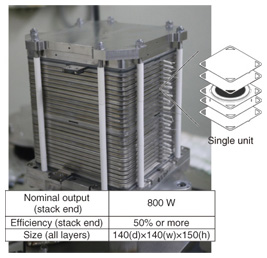
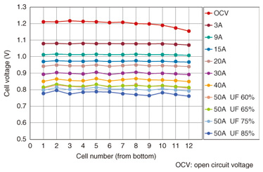
3.2 SOFC cell and stacksAn anode support structure shaped like a round plate (Fig. 6) was chosen for the cell because it can provide high output density. For the air electrode, LaNi0.6Fe0.4O3 is used, and zirconium stabilized with scandia and alumina serves as the electrolyte. Both are proprietary materials developed by NTT. These materials have very low internal resistance, and consequently, the cell has excellent output characteristics and exhibits little degradation [4]. The stack consists of single-cell units that have independent gas flow paths. They comprise multiple heat-resistant alloy separators and the abovementioned cells. The required output can be obtained by stacking the appropriate number of cell units. The 40-unit stack shown in Fig. 6 attains an output of about 1.5 kW with an efficiency of over 60% [5], [6]. We are currently investigating ways to reduce the stack size in order to improve the output power density per unit stack volume. The more compact stack is shown in Fig. 7. This stack has 30% less volume per unit output compared with the stack shown in Fig. 6, even though its performance for a single unit is the same. Characteristics for the minimized stack that is constructed with 12 single units are presented in Fig. 8. The cell units are numbered from the bottom up on the horizontal axis. The generated voltage per single unit and for various fuel consumption rates (labeled UF for utilization factor) is shown on the vertical axis. We can see from the figure that there is low variance in the voltage of each single unit, and the power generation characteristics are stable, even when the fuel consumption rate varies. Long-term continuous generation tests are currently underway, and the results obtained so far indicate a degradation rate from about 0.2–0.25% per 1000 hours during stable generation, which represents good lifetime characteristics of from four to five years of continuous use.
In the future, we will focus our efforts on reducing the size of SOFCs, extending their lifetime, and developing applications for inexpensive materials and processes in order to achieve a practical SOFC. References
|
|||||||||||||

