|
|||||||||||
|
|
|||||||||||
|
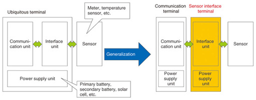
Feature Articles: Circuit and Device Technologies for Extremely Low-power Consumption for Future Communications Systems Vol. 11, No. 2, pp. 29–34, Feb. 2013. https://doi.org/10.53829/ntr201302fa5 Low-power-consumption Sensor Interface Terminal for Telemetry ApplicationsAbstractWe have developed a sensor interface terminal with low power consumption that enables various communication terminals to accommodate several sensors. In this article, we describe the concept of the interface terminal and the technologies applied to achieve low power consumption. We also give an overview of a prototype terminal and report the results of its demonstration in an actual environment.  1. Introduction1.1 TelemetryTelemetry is the collection of data from various measurement instruments through communication lines. One of the most common applications of telemetry is the remote reading of gas, water, and electricity meters. A telemetry system recently introduced in Japan for reading liquefied petroleum gas meters is now used for more than 6 million customers [1]. The system has also been applied to inventory control of vending machines, parcel delivery management, and temperature monitoring in greenhouses to improve efficiency, service, and safety [2]. The system is an M2M (machine-to-machine) service that provides communications between a server and sensors without any manual input. It primarily uses subscriber telephones and optical lines as communication lines in wired systems and the 3G (third-generation) network, PHS (personal handy-phone system), and specified low-power radio [3] in wireless systems. These communication lines are selected to match the installation environment and utilization goals. 1.2 Importance of sensor interfaceNTT Microsystem Integration Laboratories has developed low-power terminals, interfaces, and sensor circuits for ubiquitous sensor terminals. We applied these elemental technologies in a terminal used for remote reading of gas meters and for visualizing electricity consumption, and we conducted trials to evaluate the sensor terminal performance [4]. A ubiquitous sensor terminal mainly comprises a communication unit, interface unit, and power supply unit, as shown in Fig. 1. The communication unit controls connections with communication lines and accommodates various sensors through the interface unit. The power supply unit is usually equipped with a primary or secondary battery. In addition, a power generator such as a solar cell is sometimes installed to effectively use renewable energy. It is impractical to fabricate a terminal with a unique composition because the requirements for these units strongly depend on the target application, and they therefore must be generalized so they can be used in diverse conditions. Therefore, the sensor interface terminal, which mediates between a communication terminal and sensors, is very important for connecting various types of communication lines to various types of sensors.
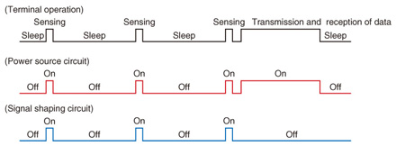
The next section describes a sensor interface terminal that we developed based on NTT’s established technologies and knowhow. 2. Sensor interface terminal2.1 OverviewWe established three main control technologies for the sensor interface terminals. The first is circuit control, which involves intermittent operation of each circuit and an interruption control. The second is data-transmission control, which reduces the frequency of transmission to a minimum by combining immediate transmission and block transmission. The third is adaptive retry control, in which data transmission is retried according to an algorithm that is matched to a characteristic or condition of a communication line. The use of these technologies leads to a battery life from five to ten years in a sensor interface terminal. 2.2 Circuit controlIn telemetry terminals, a battery life of more than a few years is generally required in order to cope with added installation sites and to reduce maintenance costs. For example, the communication units in the terminals used for remote reading of gas and water meters have very low power consumption and are powered by a battery rather than by utility power. Therefore, an equivalent battery life is required in the sensor interface terminal, which is one of the system components. To meet this requirement, the accumulated operation time is minimized by finely controlling the operation time of each circuit block, in particular, the power supply circuit and signal shaping circuit, which have relatively high power consumption. The operation profile of the terminal is shown in Fig. 2. The terminal activates both the power supply circuit and the signal shaping circuit when it obtains sensor data. The terminal turns on only the power supply circuit when it communicates with a communication terminal. Furthermore, we minimized the power consumption of the microcontroller, which controls the entire terminal, and that of the interface circuit using sleep control and an event-driven wake-up function. This control is effective because the power consumption in the sleep period strongly affects the total power consumption of the terminal when communication occurs very infrequently.
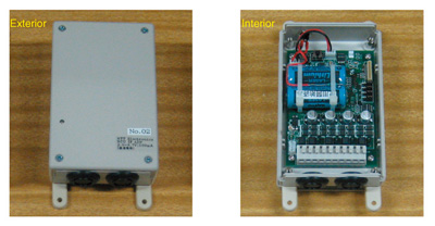
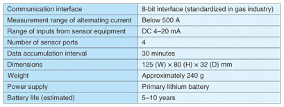
2.3 Data-transmission controlIn less demanding applications such as remote meter reading, reducing the frequency of communication is effective for reducing power consumption. By contrast, in demanding applications such as alarm systems, realtime performance is very important. In some cases, a small number of data-transmissions is desirable, for example, when a fee for the communication line is charged according to the amount of transmitted data. Transmission control that takes these factors into consideration is necessary. We established a data-transmission method to satisfy the above requirements. The terminal accumulates sensing data in its internal memory and manages them as bundled data. The terminal transmits the bundled data in a lump. The significant decrease in the overhead of data and packets reduces memory consumption, the amount of data that is transmitted, and the frequency of transmission, resulting in low power consumption. For event-driven data originating from the terminal, the terminal transmits sensing data individually without bundling to ensure realtime performance. 2.4 Adaptive retry controlThe appropriate retry control must be selected according to the application because the communication line that is used normally depends on the application. Retry control is required in order to avoid collisions between transmitted data and to minimize delay. It is important to retry data transmission when the carrier is not busy when using specified low-power radio as the communication line. We devised a method that adaptively alters the retry interval and timing according to the properties and condition of the communication line, which are estimated from the time taken to establish a link and to transmit data. An optimized retry algorithm enables the terminal to transmit data efficiently and reduces the time for retries and the total time for completing a series of data transmissions, which results in less power waste. 3. Demonstration in actual environment3.1 Prototype terminalWe applied the technologies explained in section 2 to experimentally produce a sensor interface terminal that can be accessed by a communications terminal for remote gas meter reading. Photographs of the prototype terminal are shown in Fig. 3, and the specifications are listed in Table 1. The terminal has one communication interface and four sensor ports as input/output interfaces for external devices. This enables connection with various communication terminals in order to accommodate several clamp-type alternating current sensors (CTs) and conventional sensors with analog outputs. The ability to handle up to four sensors expands the range of potential applications. Here, we selected an interface that conforms to gas industry standardization as the communication interface. The terminal operates for five to ten years with a primary lithium battery as the power supply. The long battery life makes these terminals good choices for installation in places without access to utility power.
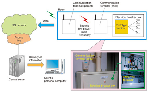
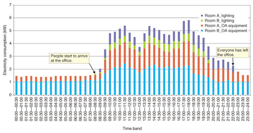
3.2 Visualization of electricity consumptionWe have been demonstrating the visualization of electricity consumption using the prototype terminal at the NTT Atsugi R&D center since August 2012. The system configuration used for the demonstration is shown in Fig. 4. The prototype terminal and three CTs are installed inside an electrical breaker box inside a room; a communication terminal with a radio is placed outside each breaker box. Seven terminals were installed in total. The communication terminals we used were commercial terminals for remote gas meter reading [5]. They consisted of a parent terminal and child terminal. The former communicates with the latter using specified low-power radio in the 429-MHz band and communicates with a central server through the 3G network and the access line. After the central server gathers and processes sensor data, it delivers information such as electricity consumption to the client PC (personal computer). An example of the observed information is shown in Fig. 5. This system visualizes the time course of electricity consumption of every circuit in each room in detail. This makes it easy to see where energy-saving actions can be promoted. In addition, we can understand various tendencies from this information. For example, electricity consumption of lighting and office automation (OA) equipment respectively indicates the presence and activity of people, whereas the electricity consumption of OA but not of lighting indicates that people are not present.
4. ConclusionWe introduced a sensor interface terminal that can be used for various telemetry applications as an example of a ubiquitous sensor terminal that uses NTT’s core technologies to achieve low power consumption. We demonstrated that the terminal allows conventional sensors to be easily connected to networks. We expect that this terminal will provide a platform that can flexibly accommodate various applications. In the future, we will promote research and development to expand the interface functions and add new functions to extend the range of applications. References
|
|||||||||||