1. Introduction
Metallic communication facilities can be said to be characterized by the following key features: 1) a huge number of facilities are currently installed in the field; 2) many years have passed since their construction; and 3) they are easily affected by weather conditions and the peripheral environment. Even today, in an era in which optical broadband facilities have become the shining star of the information-communications infrastructure, metallic communication facilities continue to play an important role as an information-communications infrastructure connecting customers. They must therefore operate effectively and achieve and maintain a certain level of service quality.
With an eye to constructing and maintaining facilities that are robust against extreme weather conditions and the peripheral environment, we present here failure cases characteristic of aerial metallic communication facilities that have been brought to the attention of the Technical Assistance and Support Center, and we explain their causes and countermeasures (Fig. 1).
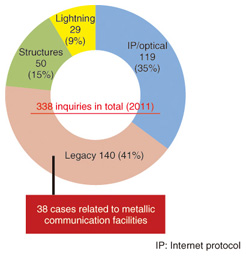
Fig. 1. Number of inquiries made to the Technical Assistance and Support Center regarding characteristic failures (FY2011).
2. Features of aerial metallic communication facilities and characteristic failures
Metallic communication facilities extend from the exchange (NTT building) all the way to the customer’s terminal via aerial and underground metallic communication facilities.
The aerial metallic communication facilities targeted here for introducing failure cases are broadly divided into (1) cable intervals and (2) connection sections. The features and typical failures of both are presented in the following (Fig. 2).
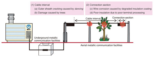
Fig. 2. Examples of failures in aerial metallic communication facilities.
2.1 Cable interval
Since the cable interval occupies most of the aerial metallic interval in terms of length of cable laid, the cable itself incorporates a certain degree of weather resistance. However, since it is naturally exposed to the peripheral environment, failures can occur such as those caused by strong winds or other types of inclement weather or by contact with trees in the immediate area.
At the initial stage of a cable-interval failure, there is often no effect on the quality of communications. This, combined with the fact that the location of such a failure is difficult to isolate, means that damage may have already spread once degraded communication service becomes noticeable. Although periodic patrols or surveys to check on facility conditions need to be performed, they require considerable work—preventive maintenance in itself is beset with problems.
2.2 Connection section
The connection section is an interval limited to the cable terminal box, but it includes coated wires in which the cable’s outer sheath is removed as well as bare conductors (copper wires) in hand-soldered connectors. It is consequently easy for the connection section to be affected by temperature, humidity, sea-salt particles, and other environmental conditions. Characteristic failures include humidity-related corrosion in wires and faulty insulation caused by deterioration of the insulator.
Similar to the cable interval, a failure in the connection section will often have no effect on communications quality in its initial stage. However, as this section is also easily affected by weather conditions, deterioration across the entire area in question may have progressed by the time that facility degradation becomes noticeable. Furthermore, in contrast to the cable interval, failures may also be caused by maintenance work.
3. Failure cases in the cable interval
and countermeasures
Here, we present examples of failures in aerial metallic communication facilities reported from various regions around Japan, and the countermeasures taken.
3.1 Outer sheath cracking (ring-shaped cut)
In regions affected by strong winds, dancing* (Fig. 3) in a self-supporting (SS) cable, especially a small-diameter one, may cause the outer sheath to crack (forming a ring-shaped cut) at the position where the cable is separated from its support line.
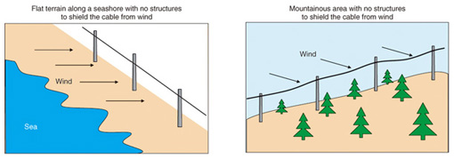
Fig. 3. Types of terrain conducive to dancing phenomenon in cables.
| * |
Dancing: A phenomenon in which an SS cable vibrates intensely from the horizontal plane due to continuous natural oscillation generated by strong wind. |
Outer sheath cracking in a color coded polyethylene (CCP) cable due to a ring-shaped cut is shown in Photo 1, and the mechanism generating this cracking is shown in Fig. 4. Along seashores or other places where there are no structures (intermediate pillars) to shield the cable from wind, the cable’s outer sheath can be damaged in a circumferential direction at the position where the cable is separated from the support line. This damage features circular fracture marks that are similar in appearance to annual growth rings in trees.
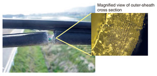
Photo 1. Outer sheath cracking by ring-shaped cut.
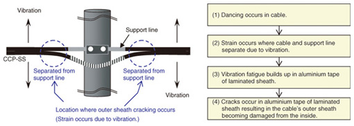
Fig. 4. Generation of outer sheath cracking in CCP-SS cable.
Countermeasures
Apply cable binding string to existing cable
This countermeasure can be applied to cable routes on which outer sheath cracking has previously occurred in CCP-SS cables because of strong winds or other factors or on routes where such damage is likely to occur. The application of cable binding string disperses the maximum strain occurring at the position where the cable separates from the support line and therefore controls the cable’s degree of freedom at the section where it is suspended at the utility pole. This produces a strain-easing effect, which is why binding using cable binding string is important (Fig. 5).
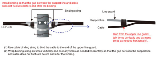
Fig. 5. Ring-shaped cut countermeasure using cable binding string.
Use high strength (HS) cable when installing new cable (or upgrading existing cable)
The use of high-strength CCP-HS-SS cable reinforced with a stainless-steel layer is an effective countermeasure against outer sheath cracking when installing new cable or upgrading existing cable when conditions (A) or (B) below apply (Photo 2).
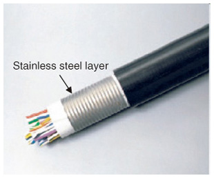
Photo 2. Appearance of HS cable.
Conditions for applying HS cable:
(A) The route is one on which cable outer sheath damage has occurred in the past because of dancing.
(B) The route is one that satisfies all three of the following conditions, indicating that outer sheath cracking may occur in the future:
(1) The area along the route has an annual average wind speed of 2 m/s or greater (according to data from the local meteorological weather station).
(2) In that area, an average wind speed of 7 m/s or greater blows in the same direction for at least half a day from fall to spring over the long term.
(3) Dancing is likely to occur at locations on the route where wind with the speed described in (2) blows with no shielding structures.
String cable through ring fixtures
In addition to the aforementioned methods, suspending the cable through ring fixtures can suppress cable dancing and prevent ring-shaped cuts.
3.2 Cable outer sheath damage
A cable can come into contact with a tree branch that rubs up against the cable’s outer sheath in such a way that even core wires can be negatively affected. An example of cable damage caused by a tree is shown in Photo 3. Although the search for faulty core wires along the span of a suspended cable can be narrowed down through a standard conduction check, isolating the exact failure location often requires a visual inspection and a great deal of labor. Some phenomena have been reported in which the damage is such that the problem can only be resolved by replacing the cable and not by simply repairing the damaged location. For example, a cable installed on an inclined route will naturally have a height difference along its span, and it has been found that core wires on the side below the damaged location can become corroded and generate disconnection failures (Fig. 6).
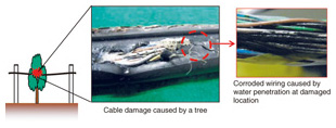
Photo 3. Example of cable damage from a tree.
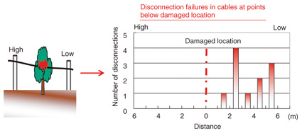
Fig. 6. Disconnection failure in cables on inclined routes.
Countermeasures
Some form of protection may be applied in locations where cables and trees come into contact with each other, or trees in the immediate area may be cut down as a preventive measure against outer sheath damage.
4. Failure cases in the connection section
and countermeasures
4.1 Core wire corrosion (insulation fractures)
Core wire insulation (polyethylene) in CCP cables can deteriorate for various reasons including high temperatures, humidity, and sea-salt particles that get inside a terminal box. Furthermore, infiltration of ultraviolet light into a terminal box through gaps caused by deformation in the terminal-box cover or side panels resulting in poor sealing—which was rarely seen in older types of terminal boxes—can accelerate such insulation degradation. Moreover, fractures have become quite noticeable in core wires in non-black colors that absorb a large portion of ultraviolet light (Photo 4).
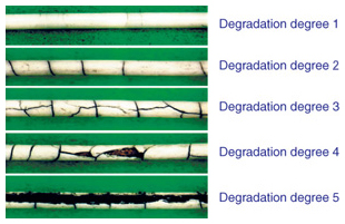
Photo 4. Classification of core wire degradation.
Countermeasures
The use of humidity controlling materials and life-extending terminal boxes can be used as countermeasures to core wire corrosion. Humidity controlling materials adjust the peripheral humidity and prevent condensation on core wires, which makes them effective in suppressing insulation degradation and failures. They are applicable to insulation that has a degree of degradation of 1 or 2. In the event of core-wire insulation having a degree of degradation of 3, 4, or 5, the existing terminal box can be replaced with a life-extending terminal box and wires inserted accordingly to ensure long-term reliability. Humidity controlling materials are shown in Photo 5, the implementation of a countermeasure to core-wire insulation faults using humidity controlling materials is shown in Photo 6, and a repair method using a life-extending terminal box is shown in Photo 7.
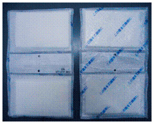
Photo 5. Humidity controlling materials.
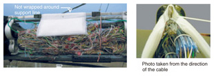
Photo 6. Countermeasure to core-wire insulation faults using humidity controlling materials.
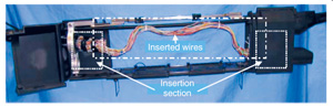
Photo 7. Repair technique using a life-extending terminal box.
4.2 Faults in terminal processing section (sleeve section)
Faults in core-wire insulation in the terminal sleeve include:
(1) Hardening faults due to insufficient stirring of the liquid A/B epoxy resin, which is used to protect the edges of core wires (naked copper wire) against humidity or other materials that can cause corrosion or unwanted contact between wires
(2) End of core wires coming into contact with the bottom of the sleeve
(3) Water penetration due to direction errors at the top and bottom of the sleeve
Examples of processing the terminal sleeve are shown in Photo 8.
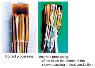
Photo 8. Examples of terminal sleeve processing.
Countermeasures
A schematic of terminal sleeve processing is shown in Fig. 7. The following points should be kept in mind when processing the terminal sleeve:
(1) Stir liquid A/B epoxy resin well so that no unreacted hardening agents remain.
(2) Let the end of core wires float about 1 cm from the bottom of the terminal sleeve.
(3) Turn the terminal sleeve upside down immediately after processing so that its bottom is oriented upward.
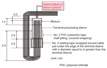
Fig. 7. Schematic of terminal sleeve processing.
5. Concluding remarks
This article introduced failure cases in aerial metallic communication facilities and countermeasures to these failures. These types of facilities are affected by weather conditions and the peripheral environment, and failures can occur for a variety of reasons. It is consequently very difficult to prevent such failures before they occur or to efficiently implement countermeasures to failures that have occurred. The Access Engineering Group of the Technical Assistance and Support Center hopes that the information provided here on failures and their countermeasures is useful in a small way to frontline personnel in facility management and in improving the maintenance of service quality.

