 |
|||||||||
|
|
|||||||||
|
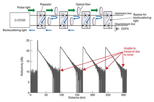
Regular Articles Vol. 12, No. 10, pp. 47–53, Oct. 2014. https://doi.org/10.53829/ntr201410ra1 Frequency-division-multiplexing Coherent OTDR for Realizing Effective Construction and Maintenance of Submarine Optical Cable SystemsAbstractWe have developed a novel coherent optical time domain reflectometry (C-OTDR) technique with the highest level of measurement sensitivity yet reported, thus enabling us to achieve the effective construction and maintenance of submarine optical cable systems. Our technique minimizes the operating time required during measurement. This article provides an overview and reports the features of our new technique, which we call frequency-division-multiplexing coherent OTDR (FDM-OTDR). Keywords: C-OTDR, submarine cable, fiber measurement 1. IntroductionSubmarine optical cable systems have been constructed and upgraded recently by employing novel transmission techniques such as digital coherent optical transmission in order to meet the demand for rapidly growing data traffic over optical trunk networks. Submarine optical cable systems are classified into two categories. One consists of repeatered systems for long-haul applications, which transmit signals over several thousand kilometers by using optical amplifiers (erbium doped fiber amplifiers (EDFAs)) and power feeding through submarine cables. The other consists of repeaterless systems for short-distance applications of up to several hundred kilometers. The fiber conditions in long-distance submarine optical cables need to be evaluated at various times including during an acceptance inspection and shipping of the cables, in a final inspection after laying the cables, and when identifying fiber faults during operation. Coherent optical time domain reflectometry (C-OTDR) [1] is normally used in such evaluations. C-OTDR is a mature technique with superior sensitivity and good characteristics for eliminating amplified spontaneous emission noise from optical amplifiers by employing coherent detection. 2. Problem with conventional C-OTDRSubmarine cable systems typically have long repeater spans for repeated systems, or a long transmission length in repeaterless systems, thanks to optical amplifiers with high total output power and low-loss optical fibers with large effective areas. C-OTDR is sensitive up to the shot noise limit of the receiver. However, one problem is that the dynamic range (DR) is sometimes insufficient when we evaluate the entire length of such submarine optical cable systems (Fig. 1). With C-OTDR measurement, a lot of time is needed to conduct a large number of iterations for averaging in order to obtain a good signal-to-noise ratio (SNR) in OTDR traces. Therefore, it is important to extend the DR in C-OTDR in order to minimize the operating time needed for cable inspection.
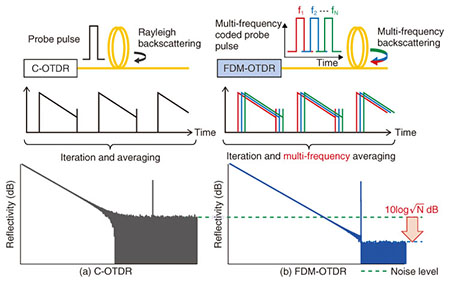
3. DR enhancement method for C-OTDRThe easiest way to extend the DR is to increase the peak power of the probe pulse from the C-OTDR. However, this does not apply to repeatered systems because the output power from the repeaters is restricted by the automatic level control function of the repeater itself. The frequency-division-multiplexing coherent OTDR (FDM-OTDR) technique we developed employs multi-frequency-coded probe pulses instead of the single-frequency pulse used in conventional C-OTDR [2]. The basic concept of our FDM-OTDR is shown in Fig. 2. A probe pulse train with N-multiple frequencies is launched into the fiber. Each frequency component is serially arranged in the time domain. These components are detected by a single photodetector, and they provide multiple OTDR traces measured at different frequencies by a fast Fourier transform (FFT). As a result, we can simultaneously obtain multiple OTDR traces measured at different frequencies. This means that OTDR traces with an SNR improved by √N can be obtained within a single iteration of the measurement. In other words, an OTDR trace with the same SNR can be obtained during an Nth part of the measurement time by using FDM-OTDR. This concept was proposed by NTT several years ago [3]. However, it required a modulator in which the probe frequency could be controlled precisely and rapidly, as well as many electronic devices at the receiver for demultiplexing the signal, which has prevented the realization of a practical system for commercial use.
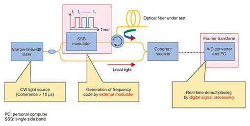
4. FDM-OTDRAn overview of the FDM-OTDR configuration we developed is shown in Fig. 3. The probe frequency of a continuous wave (CW) from one narrow-linewidth laser is controlled by an external modulator. On the receiver side, Rayleigh backscattering light with multiple frequencies is detected by a single coherent receiver and digitized with an analog/digital (A/D) converter. With FDM-OTDR, a digitized signal is demultiplexed by digital signal processing, which indicates that many electronic devices are not required. Therefore, FDM-OTDR is comparable to conventional C-OTDR in terms of size and cost. The details of the FDM-OTDR scheme are as follows.
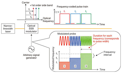
4.1 Frequency-coding of probe pulseThe frequency coding of a probe pulse on the transmitted side is shown in Fig. 4. It is performed with kHz-order accuracy by using an optical single side-band (SSB) modulator. The optical SSB modulator is controlled by using bias adjustment to modulate only the +1st order (or −1st order) component, and to suppress the carrier frequency component (CW from narrow linewidth laser) and higher order side-band components. The probe frequency is changed with a duration corresponding to the spatial resolution (namely, the pulse width in conventional C-OTDR). The number of multiplexed frequencies is limited by the receiver bandwidth. The frequency interval of the multiplexing is optimally designed in the receiver bandwidth to suppress crosstalk between frequency channels.
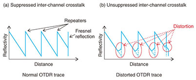
4.2 Frequency demultiplexing by digital signal processingRayleigh backscattering with multiple frequencies is detected and then digitized when a frequency-coded probe pulse is launched into an optical fiber under test (FUT). The digitized backscattered signals can be separated into each frequency component with an FFT. This signal processing is performed in real time during the round-trip time of the frequency coded probe pulse in the FUT, and it then provides the average OTDR trace from N OTDR traces. Consequently, FDM-OTDR requires significantly fewer iterations because the SNR in an OTDR trace with one iteration can be improved by √N. 4.3 Design of inter-channel crosstalkThe design of the inter-channel crosstalk in FDM-OTDR is very important because it appears as a distortion in an OTDR trace. Schematic illustrations of the distortion in an OTDR trace caused by inter-channel crosstalk are shown in Fig. 5. When we measure submarine cable systems, the reflectivity is precipitously changed with twice the gain (in dB) of the repeater. If the effect of inter-channel crosstalk greatly exceeds this reflectivity change, the shape of the OTDR trace in front of the repeater broadens as shown in the figure. This broadening in the OTDR trace can be considered degradation of the fundamental performance of OTDR measurement with respect to spatial resolution. Therefore, suppression of inter-channel crosstalk is an essential issue in FDM-OTDR. With our developed FDM-OTDR method, we employed an appropriate digital filtering technique to suppress the side lobes of the detected signals during processing. We also realized the optimal design of the frequency intervals to achieve the allowable inter-channel crosstalk and thus maintain a sufficient level of spatial resolution.
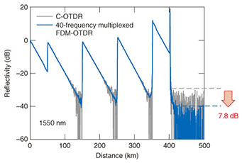
5. Characteristics in FDM-OTDRHere, we introduce an example of the measurement results we obtained using the FDM-OTDR technique with 40-frequency-multiplexing that we developed. The results of OTDR traces obtained for conventional C-OTDR and FDM-OTDR are compared in Fig. 6. The measurement conditions are the same in terms of iteration number (213) and spatial resolution (1 km). It can be seen from the figure that the round-trip DR of FDM-OTDR improved by about 7.8 dB, which agrees well with the theoretical improvement of about 8 dB (≈ 10log √N). This means that the same SNR performance can be obtained in about 1/40 the measurement time by using FDM-OTDR.
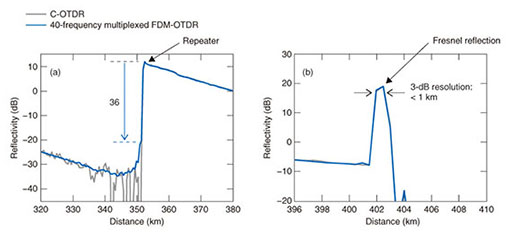
An OTDR trace obtained in front of the last repeater is plotted in Fig. 7(a), in which a huge change in the reflectivity is observed. Although we can see a marginal effect of inter-channel crosstalk when we compare conventional C-OTDR and FDM-OTDR traces, the inter-channel crosstalk is suppressed by more than 36 dB. In the Fresnel reflection in the trace obtained with FDM-OTDR at the far end of the FUT (Fig. 7(b)), it can be seen that the inter-channel crosstalk does not degrade the spatial resolution, and that we obtained the designed performance with 1 km for 3-dB spatial resolution.
As described above, our FDM-OTDR technique enables us to minimize the measurement time without any degradation in spatial resolution. 6. Future perspectivesThis article introduced FDM-OTDR with 40-frequency multiplexing, which can minimize the operating time required during the construction and maintenance of submarine cable systems. The software-based processing in the FDM-OTDR benefited from recent increases in the capacity of computer processors. We have also reported 200-frequency-multiplexed FDM-OTDR [4]. The FDM-OTDR performance, namely, the number of multiplexed frequencies, strongly depends on the performance of the hardware, for example, the A/D converter and computer processor. Noteworthy recent progress has been made on an A/D converter with a broad bandwidth and a field programmable gate array for high-speed FFT implementation. The FDM-OTDR can potentially evolve further by employing such progress. We expect FDM-OTDR to be deployed for practical applications in the near future since a short measurement time is advantageous with respect to reducing the construction and operating costs of submarine networks. References
|
|||||||||

