|
|
|
|
|
|
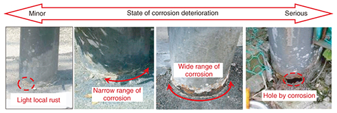
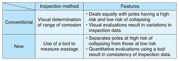
Practical Field Information about Telecommunication Technologies Vol. 13, No. 4, pp. 64–69, Apr. 2015. https://doi.org/10.53829/ntr201504pf1 Inspection Method for Near-ground Corrosion in Steel Poles for More Efficient Facility ManagementAbstractThis article introduces a method of inspecting corrosion that occurs near the ground in steel poles to achieve more efficient facility management. This is the twenty-eighth of a bimonthly series on the theme of practical field information on telecommunication technologies. This month’s contribution is from the Materials Engineering Group, Technical Assistance and Support Center, Maintenance and Service Operations Department, Network Business Headquarters, NTT EAST. Keywords: steel pole, corrosion, inspection method  1. IntroductionCorrosion that occurs on a steel pole (SP) near the ground can have a major effect on its structural strength, so SPs must be appropriately maintained and managed through facility inspections. In the past, such inspections were performed visually to evaluate the extent of corrosion near the ground and to determine whether the facility in question was failing. However, the number of deficient facilities that have been in operation for more than 30 years and that will have to be replaced is increasing, so there is a need to rethink the inspection method so that a priority can be assigned to the replacement of SPs. To this end, the Technical Assistance and Support Center has investigated a method of performing inspections to evaluate SP strength. This inspection method makes it possible to easily and quantitatively measure the degree to which an SP member is degrading due to corrosion so that facilities that require urgent handling can be identified and targeted for replacement. This article introduces the method studied here as a new and efficient approach to inspecting existing SPs. 2. Corrosion near the ground in SPs and conventional inspection methodNTT EAST and NTT WEST manage about 4 million SPs in total, and a large number of these have been in operation for many years since their initial installation. Since deterioration owing to long-term use can be visibly apparent, the approach to managing the maintenance of SPs has been to inspect their state of deterioration and to eventually replace them, starting with those with noticeable deterioration. The main cause of deterioration in communication facilities made of steel is corrosion, which is greatly influenced by the presence of water and oxygen. An SP is an outdoor facility embedded in the ground, so corrosion can easily progress on it in the area near the ground (the boundary between the above-ground and below-ground portions of the SP), where oxygen in the air is present and rain water collects. Checking the state of corrosion near the ground is therefore an important inspection task. In the conventional inspection method for this type of corrosion in SPs, the inspector visually examines the extent, or range, of corrosion or checks for holes caused by corrosion by referring to sample photographs. The inspector will then place a priority level on problem resolution (such as replacement) according to the range of corrosion (Fig. 1).
3. Understanding the actual condition of SPs judged deficientInspection using the method described in section 2 had become well established to the point that it was possible to determine the corrosion conditions at the base of SPs, but at the same time, a new problem arose. Specifically, in deciding whether replacement was necessary based on inspection results, a massive number of facilities became targeted for replacement. However, mounting a prompt response was difficult because of cost and labor considerations. In light of this situation, the cooperation of NTT branch offices and subcontractors in various areas was enlisted to survey the actual condition of deficient SPs (about 200) for which replacement was deemed necessary. This survey involved analyzing the corrosion conditions based on the progress of wastage (reduction in thickness) from corrosion, which affects the SP strength. The results of this survey revealed that almost half of the poles analyzed were affected by minor corrosion without wastage (Fig. 2). This type of corrosion does not contribute to a reduction in pole strength, so these SPs were classified as facilities not in need of prompt replacement. Thus, when the conventional inspection method was used, SPs showing no decrease in strength had been judged and managed as if they were equally deficient to SPs that did show a decrease in strength.
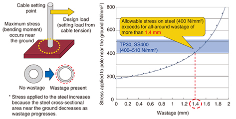
At the Technical Assistance and Support Center, we used these findings as a basis for studying inspection methods that would assess the state of an SP according to the decrease in strength associated with corrosion wastage instead of making visual judgments based on the range of corrosion near the ground. A scheme for setting priorities in replacing SPs was also studied. 4. Study of inspection methods for quantifying near-ground corrosion wastageThe strength of an SP depends on the thickness of its steel material. In addition, the stress applied to the SP increases as the cross-sectional area of the SP decreases with the progression of corrosion wastage (Fig. 3). We therefore considered the need for an inspection/management method based on the thickness of the steel material that could be applied to identify those SPs whose safety could not be ensured up to the next inspection. This could be accomplished by setting the amount of wastage at which the stress applied to the near-ground part of the SP when the SP design load is acting on the overhead position of the pole exceeds 400 N/mm2—the allowable stress on steel—as a threshold for pole replacement, and by estimating the speed of steel corrosion. Information on the steel thickness of existing SPs near the ground level is needed for this, so we studied alternative methods to visual inspection that could be used to obtain this information. In revising the inspection method in this way, we considered the importance of ensuring measurement accuracy and keeping inspection tasks simple while minimizing the costs incurred by such a revision. We tested the following two methods using commercial products.
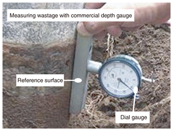
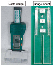
(1) Measurement of corrosion wastage using a depth gauge • This method involves measuring the depth at a near-ground location where the thickness has decreased because of corrosion, using as a reference an original (healthy) location having no corrosion on the surface of the SP (Fig. 4).
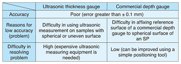
(2) Measurement of remaining thickness using an ultrasonic thickness gauge • This method involves measuring the remaining thickness at a near-ground location where thickness has decreased based on the relationship between the propagation speed of an ultrasonic pulse and its transmit/receive time. Test results revealed problems with measurement accuracy in both methods. When measurements are obtained using the depth gauge, the reference surface on the device needs to be set firmly at a sound location on the SP, but this was found to be difficult if that location had a spherical surface. By contrast, measurements obtained using the ultrasonic thickness gauge are based on the time taken for a pulse emitted from the transmit/receive sensor through one end of the steel material (incident surface) to be reflected back to the sensor from the other side of the steel material (reflecting surface). However, the reflected pulse will be difficult to measure if the reflecting surface is spherical, and an ultrasonic pulse will be difficult to insert if the incident surface is uneven. In short, problems existed with both of these measurement methods, but considering the ease (cost) of making improvements, we selected the measurement method using a depth gauge (Table 1).
5. Development of SP near-ground wastage measurement toolTo improve the accuracy in measuring corrosion wastage using a depth gauge, a function is needed for reliably positioning the depth gauge at a sound location on the SP where the material has no corrosion (expected reference surface) and also at the location of corrosion wastage. We therefore investigated a method for attaching a depth gauge mount to the SP, and after fabricating such a mount, we constructed a prototype version of an SP near-ground wastage measurement tool consisting of a depth gauge and gauge mount (Fig. 5).
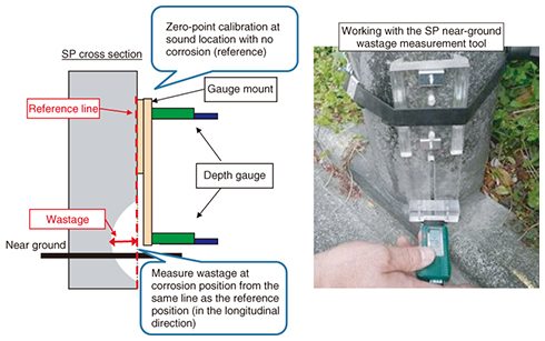
This tool uses the position of the gauge mount surface as a reference to measure the distance from the pole surface at a sound location to the pole surface at a location affected by near-ground wastage, as shown in Fig. 6. This distance is taken to be wastage (reduction in thickness). Since an SP has a tapered structure in which its diameter decreases in the upward direction (towards the top), we gave the gauge mount a shape such that the near-ground wastage location and the sound location to be measured can be positioned along the same straight line in the SP’s longitudinal direction. Furthermore, to affix the tool to the SP, we use both magnets and a fixing band. We also selected a gauge with a digital display to make measurement results easier to read in order to ease the workload on inspection personnel as much as possible. Differences between the conventional inspection method and the new inspection method are summarized in Table 2. A major difference here is that in the conventional method, the range of corrosion is evaluated by visual means, while in the new method, a measuring device is used to assess the reduction in thickness of the SP caused by corrosion (wastage).
6. Effect and acceptance of new inspection methodIn the conventional method of assessing the range of corrosion by visual inspection, SPs at a high risk of collapsing were grouped with those not at risk, which made it difficult to identify poles in urgent need of replacement. The results of a sample survey of existing SPs using the SP near-ground wastage measurement tool revealed that nearly half of the faulty SPs that had been evaluated as needing replacement by the conventional visual inspection method did not actually need to be replaced in the period up to the next inspection. Furthermore, inspections carried out using the SP near-ground wastage measurement tool enable us to finely classify SPs from those with a high risk of deteriorating and collapsing to those with no risk at all, which makes for efficient replacement and management of SPs. This new method has already been adopted as a standard inspection method, and the plan is to promote its use even further. |