|
|||||||||
|
|
|||||||||
|
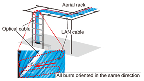
Practical Field Information about Telecommunication Technologies Vol. 13, No. 8, pp. 71–76, Aug. 2015. https://doi.org/10.53829/ntr201508pf1 Case Studies of Faults and Countermeasures in Access Telephone OfficeAbstractThis article reports on recent faults in optical access communication facilities that occurred in a telephone office. We review (1) a communication facilities problem caused by removal of a LAN (local area network) cable, (2) an accidental cable breakage that occurred while fixing cables on a distribution frame, and (3) a service interruption that occurred due to deterioration of an optical branch module used for testing optical lines. Cases (1) and (2) involved breakdowns that occurred during construction, whereas case (3) was an unforeseen breakdown related to long-term deterioration. We also present the appropriate countermeasures to these faults that were applied in order to maintain continuous operation of the communication facilities. This article is the thirtieth in a bimonthly series on practical field information on telecommunication technologies. This month’s contribution is from the Access Engineering Group, Technical Assistance and Support Center, Maintenance and Service Operations Department, Network Business Headquarters, NTT EAST. Keywords: access communication facilities, fault cases, fault countermeasures  1. IntroductionFiber-to-the-home (FTTH) systems support today’s information society and are capable of transmitting vast amounts of data. They are primarily designed with PON (passive optical network) topology [1]. When services supplied through the FTTH systems cease because of communication failures or maintenance work related to network operation, a large number of users are disadvantaged. The Technical Assistance and Support Center at NTT EAST grapples with faults that occur in access communication facilities that support the FTTH systems, and for which solutions are difficult, and develops countermeasures to the faults to improve the quality of communication facilities. Previous reports centered on actual fault cases of optical communication facilities consisting of outdoor offices and customer buildings [2–4]. This article presents recent faults in access communication facilities that occurred at a telephone office. 2. Case studies2.1 Case 1: Fault caused by cable removalThis case concerns damage to functioning cables that occurred while removing disused cables in a telephone office. (1) Fault description Multiple damage traces were discovered on the outer sheaths of optical cables and local area network (LAN) cables installed on an aerial rack. Although communication services had not yet been interrupted at the time of the discovery, the damage was extensive enough that the interior of the cables was exposed. (2) Verification results (Replication experiment) The fault location and the state of cable damage are shown in Fig. 1. The burred lines indicate the damage, and as shown, the burrs are all oriented in the same direction. In addition, each mark corresponds to an arc-shaped groove about equal in width to the diameter of the existing LAN cables. In light of the above, we inferred that the cause of the fault was an accident involving friction generated when removing LAN cables from the aerial rack. We therefore conducted a replication experiment in which we made two cables rub up against each other. Specifically, we prepared an optical cable and a LAN cable the same as those in use, and as shown in Fig. 2(a), we pulled the LAN cable over the optical cable that was fixed in place in an attempt to simulate actual cable removal work. We found that a crack began to form on the outer sheath of the fixed cable after pulling the LAN cable about 2 m and that the tension member of the cable came to be exposed after pulling the cable 10–20 m (Fig. 2(b)). We confirmed that this damage was similar to that of the original fault (Fig. 2(c)). Similar results were obtained for a LAN cable (Fig. 2(b)).
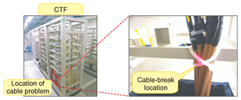
(3) Countermeasure In view of the experimental results presented above, we surmised that this fault was caused by friction generated on an optical cable or LAN cable while removing another LAN cable. We therefore considered that the use of a lubricant or anti-friction sheet at the point where the cables come in contact and generate friction would be an effective countermeasure to the friction that can accompany cable laying/removal work. 2.2 Case 2: Fault at CTF-cable binding locationThis case concerns a cut in an optical cable fixed in a cable termination frame (CTF) and the resulting break in communications. (1) Fault description A deep cut was found in a double-core optical cable laid between a CTF and on-premise equipment near the point where the cable was bound with a binding strap to other cables at the lower end of the CTF (Fig. 3). No reasons as to why the cable should be damaged near the lower end of the CTF could be found, and there was no place where the fault location could have easily come into contact with the floor.
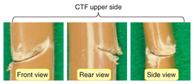
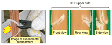
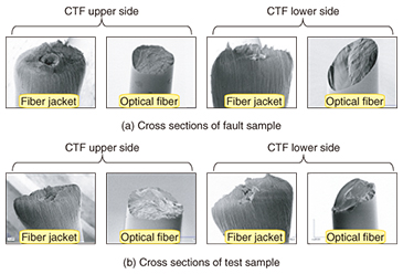
(2) Verification results (Replication experiment) On dismantling the damaged cable and inspecting its interior, we found that constituent optical cords had been cut and that the tension-member covering was damaged (Fig. 4). Consequently, we suspected that the nippers and cable clippers frequently used in fixing and removing on-premise cables might be the problem, so we examined what form of damage such tools could cause. We found that the fracture caused by nippers resembled the actual fault more closely than that caused by cable clippers. The replication setup using nippers and the damage formed in this experimental reenactment are shown in Fig. 5. Through this experiment, we found that orienting the blade tips of the nippers toward the cables when cutting the X-shaped binding strap could damage a cable as deeply as its internal optical cords. Then, on examining the fiber cross sections at the damaged location using an electronic microscope, we found that they resembled those of the fault sample as shown in Fig. 6.
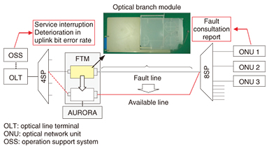
(3) Countermeasure On the basis of our observations of the damaged cable and the results of the replication experiment, we surmised that the tips of the nippers had penetrated the cable’s outer sheath when cutting the binding strap and had reached the optical-cord jacket, and that the optical fiber was sliced by the lateral pressure applied at that time. We considered that the main cause of this accident was a working environment with tight spaces and blind spots. It is therefore important that maintenance personnel make a conscious effort to orient blade tips away from cables when using nippers. In addition, cutting the binding strap from the backside of a fixing location could also be an effective measure to prevent faults of this type. 2.3 Case 3: Fault in optical branch moduleThis case concerns a fault in an optical branch module used for injecting test signals along an optical path. (1) Fault description A report of a service interruption was received from a customer using the FLET’S Hikari optical broadband service. On troubleshooting the fault, an increase in loss along the outside optical path that included an optical branch module was suspected, but the fault location could not be isolated. Although the location of the original fault had still not been clarified, it was eventually decided to switch the fault line reported as being faulty to a circuit on another optical branch module. This action effectively restored services to the customer (Fig. 7).
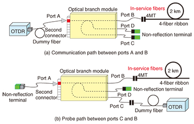
(2) Verification results (On-site inspection) Because the optical branch module targeted for inspection was accommodating other core fibers in use, we proceeded to inspect their current state in the fiber termination module (FTM) rack. First, on visually inspecting the module from the outside, we found no obvious problems in the rack or connector section. Next, we measured transmission loss between ports A-B related to the second connector cited in the fault report and also between ports C-B using an optical time-domain reflectometer (OTDR), as shown in Fig. 8. Transmission loss at the second connector of the faulty module and that of a normal one as reference are shown in Fig. 9. The transmission loss of the faulty module satisfied the specified values at standard wavelengths (1.31, 1.55, and 1.65 µm) between ports C-B but greatly exceeded the specified values between ports A-B. Furthermore, in comparison with the normal product examined in Fig. 9(b), it was found that the difference in transmission loss between port-interval A-B and port-interval C-B in the faulty module was smaller.
(3) Inference of fault location The on-premise optical branch module uses a wavelength-independent optical coupler that has an optical transmission loss difference of about 6 dB between port-intervals A-B and C-B, as shown in Fig. 9(b). However, this difference is only about 1 dB in the faulty module, as shown in Fig. 9(a), so we assumed that a fault exists for some reason at the second connector of the module. We were not able to isolate the fault in this optical branch module through fault maintenance work at the site during this investigation. We are therefore recommending that an OTDR test connecting a dummy fiber to port A of the optical branch module be conducted the next time a similar event occurs. In this way, we should be able to clarify the transmission loss between ports A-B from the difference in levels of backscattering light from the dummy fiber and outside path. This difference could then be used as a criterion for assessing problems in the module. 3. ConclusionIn this article, we introduced case studies of faults that occurred in a telephone office and explained their countermeasures. Optical communications services come in many forms, and the facilities used to support them are likewise many and varied. We can therefore expect maintenance operations for telephone offices to be just as diverse. The Technical Assistance and Support Center is committed to responding to all requests for technical consultation and assistance and to disseminating practical telecommunication technologies while leveraging the knowledge and experience gained to date from the maintenance of diverse facilities. References
|
|||||||||