|
|||||||||||||||
|
|
|||||||||||||||
|
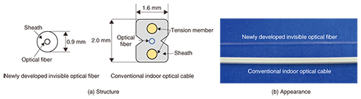
Regular Articles Vol. 14, No. 1, pp. 65–68, Jan. 2016. https://doi.org/10.53829/ntr201601ra2 Development of Invisible Optical Fiber for Improved Aesthetic AppearanceAbstractWhen optical fiber is installed on customer premises, there may be a delay in activating it if the customer complains about the conspicuous appearance of the exposed wiring. We have developed an invisible optical fiber to improve the appearance of the installed cable and to reduce the amount of unsuccessful activation work. Keywords: invisible optical fiber, attachment, fixing component  1. IntroductionExposed cable is conspicuous inside and outside buildings. There may be a delay in activating the fiber if the customer dislikes the appearance of the exposed wiring. Various measures have been implemented to correct this, for example, using cable coverings. However, any covers or other components that are used must match the wall upon which the cable is installed. This can be difficult because there are various types of walls. Therefore, we have developed an inconspicuous transparent fiber with the aim of achieving a more aesthetic appearance. The structure and appearance of the fiber is suitable for various types of walls. 2. New development conceptThe objective in developing the new fiber was to improve the outward appearance by using inconspicuous wiring. We aimed to develop wiring with the smallest possible diameter as well as a transparent color so that it would match any type of wall. Also, to improve the aesthetic appearance, we investigated a new distribution method using as few connection points as possible. However, the thin cable may have inferior impact resistance characteristics. Therefore, we also investigated a new installation method that uses the distribution method mentioned above along with peripheral components. 3. Product development3.1 Invisible optical fiberTo improve the visible appearance of optical fiber cabling, we developed a transparent cable sheath instead of using the conventional black and white cable. In addition, the structure is thinner than conventional cable, with a diameter of 0.9 mm (Fig. 1). This product is suitable for use in restricted spaces; it can be installed in the gap around a door, for example, which is only about 2 mm wide. To install optical cable in such a small gap, we employed single-mode hole-assisted fiber (HAF) with bending-insensitive characteristics. When wiring, we use a dedicated tube in order to ensure the bending radius. The dedicated tube is also transparent (Fig. 2).
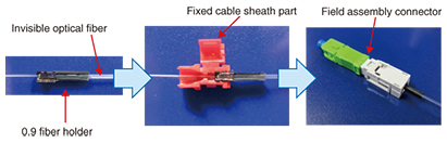
3.2 Connection techniques for invisible optical fiberWe developed techniques to connect the invisible optical fiber using two different materials: (1) Fiber holder We developed a 0.9 fiber holder to attach the field assembly connector to the invisible optical fiber. The cross-section size of the invisible optical fiber and the conventional indoor optical cable are 0.9 mm in diameter and 2.0 × 1.6 mm, respectively. Using the 0.9 fiber holder enables the invisible optical fiber to be the same cross-section size as the conventional indoor optical cable. The connector assembly procedure for an invisible optical fiber and the 0.9 fiber holder is shown in Fig. 3.
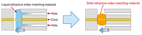
(2) Solid refractive index matching material We used single-mode HAF based on ITU-T* G.657 B3 for the invisible optical fiber. A liquid refractive index matching material is used to ensure that the splicing characteristics in the field assembly connectors are sufficient. When we splice the HAF using the liquid refractive index matching material, the splice loss characteristics are degraded. This is because the matching material penetrates the air holes in the HAF, and a void is formed between the fiber end faces. This problem can be solved by using a solid refractive index matching material. Thus, we used the solid refractive index matching material with the field assembly connector for invisible optical fiber consisting of HAF. The HAF splice components with liquid and solid refractive index matching materials are illustrated in Fig. 4.
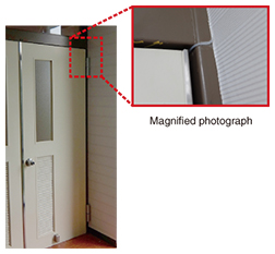
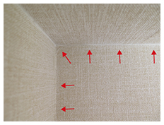
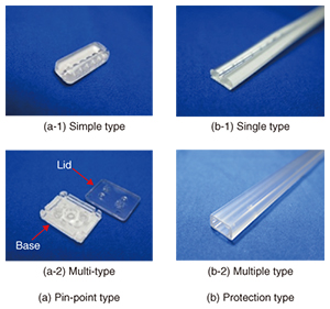
3.3 Wiring techniqueThe wiring route was in a corner of the wall. Cable wiring is inconspicuous when installed in the corner (Fig. 5). To further improve the aesthetics of the room, we used transparent fixing components. The fixing components are available as a pin-point type or protection type (Fig. 6), and both of these types are also sorted into two styles. The pin-point type is sorted into the simple and multi-types. The top priority with the simple type is to achieve a small size, which makes it inconspicuous. This component is fixed in place with double-sided tape. The multi-type can be fixed to different kinds of walls with double-sided tape, plaster pins, or screws. We also developed two styles for the protection type fixing components, as shown in the figure. As mentioned previously, invisible optical fiber is inferior in impact resistance because it has a smaller diameter than that of the indoor optical fiber currently used. Consequently, we developed a single-type fixing component of the protection type to be used in areas where it is likely to be touched by customers. The protection-type of fixing component is also available in a multiple type, providing greater flexibility.
4. ConclusionWe introduced in this article our newly developed invisible optical fiber. We will continue to promote the introduction of optical fiber in cooperation with business companies and to support the business companies in deploying the fiber.
|
|||||||||||||||