|
|
|
|
|
|
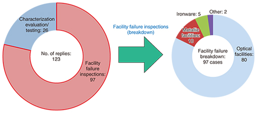
Practical Field Information about Telecommunication Technologies Vol. 14, No. 2, pp. 54–58, Feb. 2016. https://doi.org/10.53829/ntr201602pf1 Case Studies of Failures and Countermeasures in Access Network FacilitiesAbstractThis article describes case studies of failures and countermeasures in access network facilities. This is the thirty-third article in a bimonthly series on practical field information on telecommunication technologies. This month’s contribution is from the Access Engineering Group, Technical Assistance and Support Center, Maintenance and Service Operations Department, Network Business Headquarters, NTT EAST. Keywords: access network facilities, failure case studies, damage caused by wildlife  1. IntroductionNTT’s access network facilities are deployed throughout the country, with most installed in outdoor environments. As a result, failures occur every year because of weather factors such as rain, wind, snow, and lightning; the harmful effects of special environments containing salt, sulfidizing gas, or other elements; and damage caused by wildlife. In fiscal years 2013 and 2014, the Technical Assistance and Support Center received 97 inspection requests in relation to access network facilities (Fig. 1). We introduce three of these cases in this article.
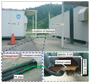
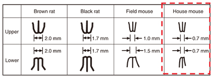
2. Introduction of failure case studies2.1 Optical cable breakage2.1.1 OverviewDisconnections in optical links between node equipment housed in remote terminal (RT) boxes occurred twice over a period of two days. An inspection performed by the local maintenance department revealed damage at a particular location in optical cable drawn between the RT boxes. 2.1.2 Inspection results and inference of causeThe optical cable between the RT boxes was drawn inside hard polyethylene (PE) pipe covered by a concrete U-shaped conduit. In this case, a 5 × 4 cm hole was discovered in one of three PE pipes within which tree leaves were scattered about (Fig. 2). A digital microscope was used to observe the optical cable and the PE pipe at the damaged location. This observation revealed incisor teeth marks (two upper teeth 0.7 mm in width and two lower teeth 0.6 mm in width) thought to be those of rodents. The widths of the teeth led us to infer that the damage-inflicting wildlife was a small rodent such as a house mouse (Fig. 3).
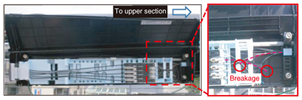
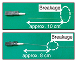
2.1.3 CountermeasureAs a countermeasure to damage caused by wildlife, it is important that facilities that require protection not be exposed. In this case study, it is thought that an animal penetrated the U-shaped conduit and gnawed on the cable in the process of building a nest inside the PE pipe. We therefore recommend that the entrance to a U-shaped conduit or any other location of penetration be sealed off and that any locations where wildlife-related damage has occurred in the past be periodically inspected. 2.2 Fiber breakage within optical closure2.2.1 OverviewBreakage of an optical fiber occurred in two optical fiber cables within an optical drop closure at the bottom of an outdoor 8-branch splitter. An inspection performed by the local maintenance department revealed that the two failures occurred at the same time according to the monitoring-system log and that core fibers suffered breakages 8–10 cm from splice-on connectors within the closure (Figs. 4 and 5).
2.2.2 Inspection resultsThe splice-on connectors connected to the damaged fibers were visually examined, and no damage or other anomalies were found. The surfaces of the fractures in the fibers were then observed by scanning electron microscope, and it was found that the fibers fractured at an angle (Table 1).
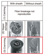
2.2.3 Reproducibility experiment and inference of causeIn this case study, it was assumed that some type of external force during construction was applied to the core fibers, which caused the fractures. We performed a reproducibility experiment for three types of external forces caused by (1) catching the optical fiber on the closure frame, (2) damaging the optical fiber with nippers, and (3) cramming the fiber into position with the closure lid (Table 2). The results revealed that the fractures could not be reproduced by external force (1) and that the fracture surface took on a mountain shape by external force (2). However, for external force (3), although a cramming effect could not be achieved using existing work procedures, it was possible to reproduce the shape of the fractured fibers in this case study when using procedures outside of installation standards. In an optical drop closure with splice-on connectors, the excess cutoff length of fiber cores (cutting position) is predetermined, but if the cutoff position is longer than that predetermined length, it is known that the surplus length of the fiber core may protrude from the closure when being stowed and end up being crammed in by the closure lid. The fracture of a crammed-in optical fiber is diagonally shaped, and since that was similar to the received fractured sample, it was concluded that the type of fracture in this case study was caused by an external force such as cramming applied to a core fiber that had been cut off at the wrong position.
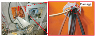
2.2.4 CountermeasureOptical fibers are vulnerable to scratches, cuts, and bends, so they should be handled with the utmost care. We recommend that stipulated surplus lengths be observed when assembling a connector and that sufficient caution be taken to prevent fibers from getting crammed in when opening or closing the optical closure. 2.3 Breakage in 4T indoor optical cable in building pipe2.3.1 OverviewWhen new optical cable was drawn through a pipe already containing optical cables (indoor optical fibers) in a customer’s main distribution frame (MDF) room, a breakage occurred in the existing optical cable. 2.3.2 Results of on-site inspectionThe pipe opening through which optical cables pass in the MDF room was installed in the downward direction at a height about 60 cm from the floor, and it was found that a portion of the edge of the pipe opening had been chipped away (with a width of about 10 mm), as shown in Fig. 6. In addition, the damaged optical cable suffered a breakage near the pipe opening. This breakage took the form of groove-shaped damage with a maximum width of 3.7 mm that occurred at an angle to the longitudinal direction of the cable.
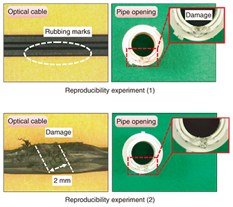
2.3.3 Reproducibility experimentsWe conducted reproducibility experiments to isolate the cause of this breakage. First, we inserted 15 m of a threading wire (6.5 mm in diameter) into a pipe in which multiple optical cables already existed and pulled it out while in contact with the pipe opening, repeating this process three times. In each case, only rubbing marks appeared on the outer sheath of the existing optical cables, but it was found that the edge of the pipe opening was damaged in the form of groove-shaped chipping similar to the damage in the on-site pipe (Fig. 7 (1)). We then conducted another experiment, this time by fitting existing optical cable into the groove-shaped damaged section of the pipe opening and again inserting and pulling out a threading wire three times. For two of the three times, we found that we were able to reproduce the state in which the outer sheath of the existing optical cable was scraped away to expose the optical fiber (Fig. 7 (2)).
2.3.4 Inference of causeThe results of the inspection and reproducibility experiments led us to infer that this type of failure occurred in the following process. 1) When performing threading operations through a pipe using a threading wire in the past, contact between the edge of the pipe opening and the threading wire generated friction that eventually damaged the pipe opening. 2) Then, when performing threading again in a state in which an existing optical cable was stuck in place within the damaged edge of the pipe opening, the optical cable and the threading wire rubbed against each other, thereby damaging the optical cable. 2.3.5 CountermeasureIt is important that care be taken so as not to damage existing facilities during work operations. For the type of failure presented in this case study, we recommend that field personnel use threading wire carefully so as not to damage pipe openings and that they pay attention to the state of existing cable. 3. ConclusionThis report introduced case studies of failures in access network facilities and their countermeasures. By leveraging its knowledge and experience in the maintenance and operation of diverse facilities accumulated over many years, the Technical Assistance and Support Center will continue to handle requests from all concerned for technical consultation, assistance, and support and to provide information on ways to further improve the reliability of access network facilities. |