|
|
|
|
|
|
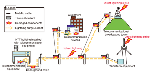
Practical Field Information about Telecommunication Technologies Vol. 14, No. 7, pp. 67–71, July 2016. https://doi.org/10.53829/ntr201607pf1 Improvements in Cable Surge ProtectorsAbstractSerious damage in telecommunication facilities can occur due to lightning surges. Cable surge protectors are effective in reducing the damage to telecommunication facilities caused by penetration of lightning surges to metallic cables. This article introduces the improvements that have been made to new cable surge protectors developed by NTT EAST. This is the thirty-fifth article in a series on telecommunication technologies. This month’s contribution is from the EMC Engineering Group, Technical Assistance and Support Center, Maintenance and Service Operations Department, Network Business Headquarters, NTT EAST. Keywords: lightning damage, cable surge protector, surge current  1. IntroductionCable surge protectors are typically used to reduce lightning damage to telecommunication facilities. Nevertheless, the work required to install these devices is time-consuming. Moreover, ensuring there is sufficient installation space within terminal closures is required because the number of cable surge protectors to be installed depends on the total number of core wires in the target cable. We have therefore developed a new, more compact cable surge protector that improves connection workability. The following sections introduce this new surge protector. 2. Lightning damage to telecommunication facilitiesTall antenna towers are built on telecommunication buildings, and consequently, these towers are often struck by lightning. Metallic cables are connected to the telecommunication buildings that accommodate subscribers or have telecommunication or broadcasting towers, and also to wind farms or other structures. These cables are vulnerable to the surges caused by direct lightning strikes flowing into the telecommunication facilities. An example of damage to telecommunication facilities caused by lightning surge current is shown in Fig. 1.
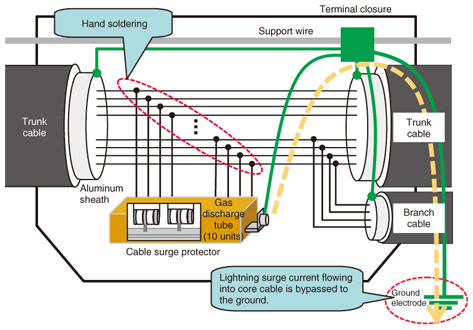
Surge current caused by direct lightning strikes on steel towers or windmills flows into metallic cables. This current often damages the telecommunication equipment installed in NTT buildings, the telecommunication devices in customer premises, and also the metallic cables themselves and their connection points. Lightning damage in metallic cables is caused by an insulation breakdown between core wires or between a core wire and the cable’s aluminum sheath. In addition, indirect lightning surge current can occur in metallic telecommunication cables when lightning strikes nearby power lines or trees, or when inter-cloud discharges occur. 3. Overview of cable surge protectorA cable surge protector can bypass surge current to a ground electrode through multiple connections to the core wires of a metallic cable. The connection configuration of the cable surge protector is shown in Fig. 2.
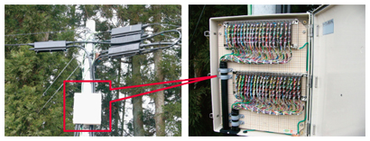
3.1 Connection of cable surge protectorThe cable surge protector is connected by splicing it to each of the core wires. For greater lightning protection, the protector is connected by hand soldering it to core wires, instead of using pair transferable splicing (PAT) or multiple connectors. Each cable surge protector unit can be connected to ten pair wires. All core wires must be connected to a cable surge protector in order to prevent insulation breakdown between the core wires. This means that multiple surge protectors may be needed depending on the number of core wires. Recommended locations for installing cable surge protectors are the terminal closure at the cable pull-in pole on steel towers and wind turbines, which are metallic cable branching points, and the locations where core wires of different diameters are connected. Cable surge protectors should be installed in terminal closures placed at 500-meter intervals along a cable route. 3.2 Effects of using cable surge protectorLightning surge current that flows into the core wires of the cable is released to a ground electrode via a gas discharge tube installed in the cable surge protector. This function protects the metallic cable and telecommunication facilities. It also prevents the insulation breakdown between the core wires themselves and between core wires and the aluminum sheath. When surge current due to a direct lightning strike with a large amount of energy exceeds the capability of the cable surge protector, the protector may break down. The cable surge protector can limit the area where the lightning damage occurs because it can bypass the surge current to a ground electrode. 4. Issues with existing cable surge protectorsPAT connectors are generally used to connect the core wires of metallic cable. However, such connectors may be damaged in the locations where surge current due to direct lightning strikes occurs. A cable surge protector must therefore be connected to each core wire by hand soldering, which is very time-consuming. Moreover, since all core wires must be connected, the number of cable surge protectors to be installed depends on the total number of core wires in the target cable. Therefore, it is necessary to ensure there is a sufficient installation space within a terminal closure. When the cable surge protectors cannot be installed in a terminal closure, it is possible to use cable surge protectors that are enclosed in a dedicated box for external use, which are installed on a utility pole. A dedicated-box-type cable surge protector is shown in Fig. 3.
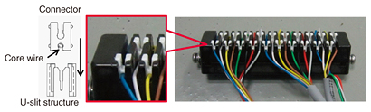
In summary, cable surge protectors can be very effective to prevent lightning damage to metallic cables. The two key issues are that the connection task is very time-consuming and that sufficient installation space is needed. 5. Improvements to cable surge protector5.1 Improving connection workabilityA new connection method for a cable surge protector to simplify the connection task was investigated. The new connection method is shown in Fig. 4.
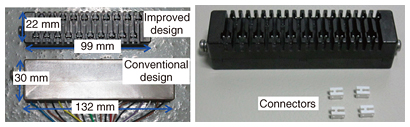
This method adopts U-slit structures for the improved cable surge protector. This connector can accommodate up to 20 core wires. The core wires were connected by crimp connection, which does not require dedicated connection tools. Core wires with diameters of 0.65 mm and 0.9 mm can be connected to the protector. (In terms of lightning protection, core wire diameters greater than 0.65 mm are preferable.) The crimp connection is made either at the top or bottom of the connector depending on the diameter of the core wire. In addition to improving connection workability, the use of crimp connection can also contribute to safer work operations because no soldering iron is needed. 5.2 Downsizing installation spaceA means of downsizing the configuration of the cable surge protector to ensure sufficient installation space within the terminal closure was also investigated. An external view of the improved cable surge protector is shown in Fig. 5. To achieve a more compact cable surge protector, a new type of gas discharge tube (GDT), which is a major component of a surge protector, was developed. The conventional GDT design consisted of 2 signal electrodes and 1 ground electrode, making for a 3-electrode GDT for each core wire. In the new design, 10 signal electrodes and 1 ground electrode into an 11-electrode GDT for 5 core wire pairs were consolidated. This new GDT achieved performance equivalent to that of the conventional GDT, but with much less degradation, because it has a common internal arrester space (gap) instead of separated gaps. In this way, the main body of the cable surge protector can be made smaller because the new GDT size is smaller than the conventional one. Specifically, the dimensions of the cable surge protector were reduced from 132 × 30 × 15 mm to 99 × 22 × 19 mm, resulting in the volume approximately 30% smaller than that of the conventional product.
6. Functional verificationAs described above, the improved cable surge protector adopts U-slit structures in the connecting section, a multi-electrode configuration, and a downsized enclosure. Therefore, there were concerns that this new structure might have less resistibility to lightning surge current than the conventional product. Accordingly, the resistibility to lightning surge current of the improved cable surge protector by using a prototype unit and the conventional one were compared. Specifically, we tested the maximum resistibility to surge current using a direct lightning strike surge current generator between all telecommunication line ports and the ground port, between each telecommunication line port and the ground port, and between telecommunication line ports themselves. The results of these tests showed that no sparks or other problems occurred at the U-slit connection sections, contact points, or unused points, as a result of enclosure downsizing, and that the maximum resistibility to surge current was nearly equivalent to that of the conventional cable surge protector. These results indicate that an effective new cable surge protector that improves connection workability and downsizes the unit enclosure was achieved. The resistibility to lightning surge current of the new cable surge protector is the same as that of the conventional cable surge protector. 7. ConclusionThis article introduced a new downsized cable surge protector that improves workability. The plan going forward is to carry out trials in the field and to commercialize a surge protector product reflecting the results of these trials. The EMC Engineering Group of the Technical Assistance and Support Center is committed to the smooth provision of telecommunication services and to achieving prompt solutions aimed to reduce the amount of lightning damage. To this end, we intend to actively focus on technology development, technology collaboration, and technology seminars. |