|
|||||||||||||||
|
|
|||||||||||||||
|
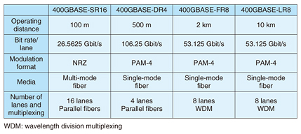
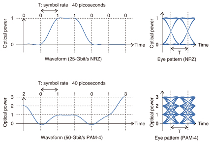
Feature Articles: Device Technology Development for Beyond 100G Optical Transport Network Vol. 14, No. 9, pp. 18–23, Sept. 2016. https://doi.org/10.53829/ntr201609fa4 High-sensitivity 4-channel Receiver Module with Avalanche Photodiode for 400-Gbit/s EthernetAbstractWe developed an integrated 4-channel receiver optical subassembly (ROSA) with high-sensitivity avalanche photodiode (APD) for 400-Gbit/s Ethernet. A minimum receiver sensitivity of –21.2 dBm with a 4-channel × 28-Gbaud PAM-4 (four-level pulse amplitude modulation) APD-ROSA was achieved, enabling us to achieve 30-km transmission. Keywords: avalanche photodiode (APD), 400-Gbit/s Ethernet, receiver optical subassembly (ROSA)  1. IntroductionData traffic both within and between datacenters is rapidly increasing as the demand for cloud computing, video streaming, and mobile services grows. To cope with this demand, the Institute of Electrical and Electronics Engineers (IEEE) is currently discussing the standardization of 400-Gbit/s Ethernet [1] as the next-generation standard following 100-Gbit/s Ethernet. The bit rate/lane and modulation format of each operating distance in 400-Gbit/s Ethernet using an optical fiber are listed in Table 1. The 400-Gbit/s Ethernet is the first to employ a higher-order modulation (HOM) format for the Ethernet optical data transmission. The optical modulation format currently employed is non return to zero (NRZ); however, 400-Gbit/s Ethernet employs a four-level pulse amplitude modulation (PAM-4) as a kind of HOM format. While an NRZ signal consists of two levels (0 and 1), PAM-4 consists of four levels (0, 1, 2, and 3), as shown in Fig. 1. Therefore, the transmission of a PAM-4 signal can achieve twice the bit rate of the NRZ signal under the same baud rate.
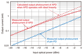
The standardization of 400-Gbit/s Ethernet is based on operating distances up to 10 km. However, the possibility of extending the operating distance has been discussed to cope with the increasing capacity of inter-building links and mobile backhaul [2]. Extending the operating distance will require enlarging the power budget from transmitter to receiver. One promising method to do this is to improve sensitivity using an avalanche photodiode (APD). Applying an APD to a receiver not only achieves a high-sensitivity receiver thanks to inner gain, but also a compact receiver thanks to its low power consumption [3]. 2. Linearity of APD receiver optical subassembly (APD-ROSA)In systems with the PAM-4 signal, photodiodes are required to achieve high linearity of an output photocurrent against the optical input power. While APDs can deliver high performance in terms of responsivity, they exhibit higher nonlinearity than p-i-n photodiodes (pin-PDs) in direct current (DC) input and output characteristics due to both the thermal effect and the space charge effect [4]. Consequently, in order to employ APDs in the PAM-4 system, it is necessary to measure the linearity of an APD receiver using a linear-type transimpedance amplifier (TIA) and confirm the degree of nonlinearity. The measured output photocurrents in a pin-PD and our APD and the calculated output photocurrent when the APD operates with the ideal linearity are plotted in Fig. 2. As indicated by the solid red curve and the dashed red line, the gap between the red curve and the line increases as the input optical power is increased. These results show that our APD has nonlinearity in DC input and output characteristics. If the waveform of the optical PAM-4 input is converted to an electrical signal in accordance with DC input and output characteristics of the APD, one concern is that the amplitude of the upper inner-eye would become smaller than that of the middle and lower inner-eyes, resulting in bit error rate (BER) degradation.
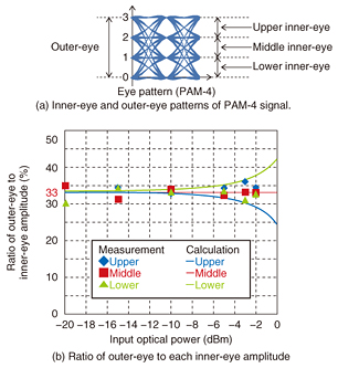
To evaluate the effect of DC nonlinearity on the optical-to-electrical (O/E) conversion of PAM-4 signals, we measured the ratio of each inner-eye amplitude to the outer-eye amplitude, as shown in Fig. 3(a). To simplify the measurements, we used an experimental baud rate of 10 Gbaud and a PAM-4 modulation format. The measurement results are shown in Fig. 3(b). The solid curves are the ratios calculated from the DC input and output characteristics of the APD. In the calculation, the extinction ratio (ER) of the outer-eye is assumed to be 4.8 dB. The calculated values deviate by 9% from 33% for the average received power of 0 dBm due to the DC nonlinearity. In contrast, the measured ratios stay at 33%, which is within the range of measurement error, regardless of the received optical power. These results indicate that the O/E conversion of PAM-4 signals does not seem to be affected by DC nonlinearity for average received powers up to –2 dBm.
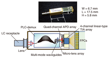
3. APD-ROSA for 400-Gbit/s Ethernet systemsA photograph and schematic view of a 4-channel APD-ROSA, which can receive 200-Gbit/s (4-channel × 28 Gbaud × PAM-4) signals are shown in Fig. 4. The APD-ROSA consists of a planar lightwave circuit demultiplexer (PLC-demux), a quad-channel APD array, and a linear-type TIA array. An LC receptacle and flexible printed circuits (FPCs) are respectively attached to the optical wavelength-division multiplexing (WDM) input and electronical output. The optical coupling between the PLC-demux and APD array employs a low-loss technique using both the multi-mode waveguide and micro-lens array developed for a 100-Gbit/s Ethernet ROSA [5]. The input 4-wavelength × 28-Gbaud PAM-4 optical signal is demultiplexed into four wavelengths in the PLC-demux. In the quad-channel APD array, the optical signals are converted to electrical signals and fed into the linear-type TIA array. Then, amplified 4 × 28-Gbaud PAM-4 signals are output from the linear-type TIA array. The package size is as small as 17.5 × 6.7 × 5.8 mm in order to install two modules in a CFP8 (centum (100) gigabit form-factor pluggable 8) [6] transceiver (107.5 × 40 × 9.5 mm) for 400-Gbit/s operation. The total power consumption of the APD-ROSA is as low as 860 mW at room temperature.
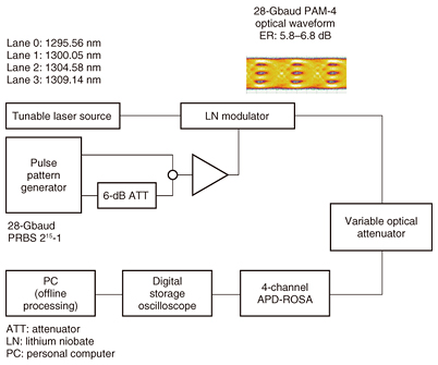
The performance of the 4-channel APD-ROSA in receiving PAM-4 signals was investigated in a back-to-back configuration. The experimental setup is shown in Fig. 5. The input optical signal from a tunable laser source was modulated using a lithium niobate Mach-Zehnder modulator with a 28-Gbaud PAM-4 signal of a 215-1 pseudo random bit sequence (PRBS). The wavelengths for lanes 0, 1, 2, and 3 were respectively set at 1295.56, 1300.05, 1304.58, and 1309.14 nm. The ER of the outer-eye for lanes 0, 1, 2, and 3 was 5.6, 6.4, 6.0, and 6.8 dB, respectively. The PAM-4 signal was received and converted to the electrical signal by the APD-ROSA and then input into a digital storage oscilloscope with 33-GHz analog bandwidth and a sample rate of 80 GSample/sec. We demodulated the stored signal by offline digital signal processing, in which we used a half-symbol-spaced adaptive equalizer with 17 taps. A variable optical attenuator was inserted before the APD-ROSA to change the input power.
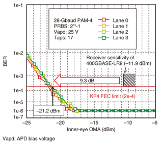
The BER measurement results for single-channel operation of each lane are shown in Fig. 6. We observed a minimum receiver sensitivity better than –21.2 dBm in optical modulation amplitude (OMA) of the inner-eye for all channels at a BER of 2e-4, assuming the Reed-Solomon forward error correction (544, 514) defined in 100GBASE-KP4 (IEEE 802.3bj) [7]. The symbols plotted on 1e-6 show that no bit error is observed within the stored data length. This minimum receiver sensitivity has a margin of 9.3 dB for the sensitivity (–11.9 dBm) required in 400GBASE-LR8. This margin would enable 400-Gbit/s transmission with an extended operating distance up to 30 km, assuming a 0.4-dB/km loss of single-mode fiber.
4. ConclusionWe developed a 4-channel APD-ROSA as a key component to achieve 400-Gbit/s Ethernet. The APD-ROSA is integrated using a quad-channel APD array, PLC-demux, and linear-type TIA. We investigated the linearity of the APD-ROSA for PAM-4 signals and confirmed that three inner-eye amplitudes of the output waveform were kept equal up to –2 dBm. We also successfully demonstrated 28-Gbaud operation with a minimum receiver sensitivity of –21.2 dBm or below for PAM-4 signals. This result indicates that with an assumed 0.4-dB/km loss of a single-mode fiber, the APD-ROSA is a promising device to achieve 400-Gbit/s data transmission up to 30 km or longer. References
|
|||||||||||||||