|
|||||
|
|
|||||
|
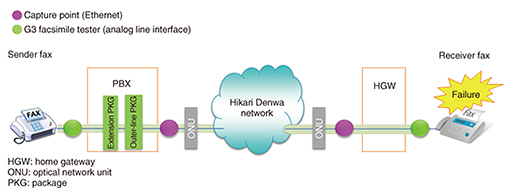
Practical Field Information about Telecommunication Technologies Vol. 15, No. 2, pp. 38–42, Feb. 2017. https://doi.org/10.53829/ntr201702pf1 Fax Transmission Failure Analysis Method Requiring Multi-signal AnalysisAbstractThis article describes a problem a customer had involving facsimile transmission failure and how it was resolved through analysis of multiple signals. This is the thirty-eighth article in a series on telecommunication technologies. This contribution is from the Network Interface Engineering Group, Technical Assistance and Support Center, Maintenance and Service Operations Department, Network Business Headquarters, NTT EAST. Keywords: facsimile, IP network service, echo  1. IntroductionThe Network Interface Engineering Group provides technical support in relation to Internet protocol (IP) network services such as FLET’S HIKARI NEXT. This includes analyzing the Ethernet interface between terminal equipment and telecommunications equipment as well as analog line and ISDN (Integrated Services Digital Network) interfaces comprising gateways and private branch exchange (PBX) equipment. We introduce here a case study in which we applied our analysis methods to determine why a Group 3 (G3) facsimile (fax) machine accommodated by PBX equipment would sometimes fail to transmit fax data to a specific party. 2. Case study overview and investigation methodThe customer was using a G3 fax machine connected to PBX equipment. The customer found that the transmission of fax data from this machine to a specific party would occasionally fail. The approach taken by maintenance personnel in past cases of fax machine transmission problems was to replace the outer-line package for Hikari Denwa use or the extension package for fax use housed within the PBX equipment, or to change the transmission level of the fax signal. This time, however, the problem could not be solved with that approach, and the Technical Assistance and Support Center was asked to investigate the cause of the problem. To collect data at the time of failure occurrence, we installed packet capture equipment in the Ethernet interval and a G3 facsimile tester in the analog line interface and proceeded to collect and analyze IP packets and fax signals (Fig. 1).
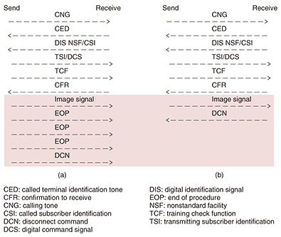
3. Analysis of collected data(1) Ethernet No anomalies were found in the Session Initiation Protocol (SIP) communication sequence for Hikari Denwa call control. In addition, no packet losses or abnormal packet arrival intervals that could cause the failure could be found in the Real-time Transport Protocol (RTP) packets carrying the fax signal. (2) Analog line interface The sender fax communication sequence of the reporting customer and the receiver fax communication sequence of the other party as collected by the G3 facsimile testers are shown in Fig. 2.
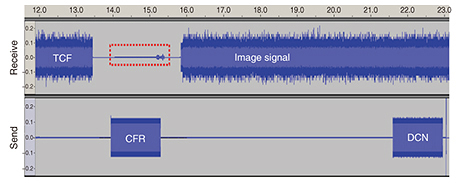
(3) Sender fax communication sequence The sender fax sends an EOP (end of procedure) signal after sending the image signal. However, as no MCF (message confirmation) signal is received from the receiver fax, the sender fax sends a DCN (disconnect command) signal and disconnects the communication (Fig. 2(a)). (4) Receiver fax communication sequence After receiving the image signal, the receiver fax sends a DCN signal before receiving an EOP signal from the sender side and disconnects the communication (Fig. 2(b)). Therefore, we conducted a detailed analysis to find out why the receiver fax was disconnecting in this manner. 4. Analysis of audio data using AudacityWe extracted RTP packets from captured Ethernet data on the receive side at the time of failure and analyzed the audio files saved for each call made and received using Audacity*1 software. In our analysis, we found a particular signal that could not be recognized by the G3 facsimile tester (Fig. 3, red-framed box).
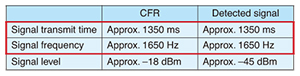
This signal differed from the TCF (training check function) signal and image signal transmitted by the sender fax, while it had the same signal transmit time and signal frequency as the CFR (confirmation to receive) signal transmitted by the receiver fax (Table 1, red-framed box).
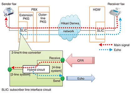
The above results suggest that this signal was an echo*2 of the CFR signal transmitted by the receiver fax and that it originated in the extension package of the PBX equipment on the sender side (2-line/4-line converter), as shown in Fig. 4.
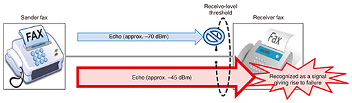
5. Cause of failureIt was thought that a CFR echo of approximately –45 dBm or greater generated in the extension package of the PBX equipment (2-line/4-line converter) would exceed the receive-level threshold of the receiver fax. This echo would consequently be erroneously recognized as a signal from the sender fax, causing this failure to occur. The signal level of the CFR echo during normal operation was approximately –70 dBm (Fig. 5).
6. CountermeasuresWe considered that the receive-level threshold of the receiver fax could be raised so that the echo would not exceed that threshold, or that the transmit level of the receiver fax could be lowered so as to reduce the echo and prevent it from being recognized as a valid signal. However, because the receiver fax was a model for which the receive-level threshold could not be changed, we lowered the transmit level in 1-dB increments and found that lowering it by 2 dB was enough to prevent the reoccurrence of this event. We considered that this was because the echo would no longer exceed the receive-level threshold of the receiver fax at that transmit level, thereby preventing the echo from being mistakenly recognized as a signal from the sender fax. 7. ConclusionIn IP network services, devices with analog line or ISDN interfaces may be used in configurations consisting of gateways and PBX equipment. Solving problems in such configurations requires a combination of measurement equipment and analysis methods for each type of interface. The case study presented here showed how analyzing analog line interface signals and Ethernet data made it possible to solve a puzzling problem. Going forward, the Technical Assistance and Support Center aims to continue its work in solving difficult problems through the use of diverse tools and the analysis of signals and data for a variety of interfaces. |
|||||