|
|||||
|
|
|||||
|
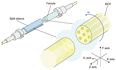
Feature Articles: State-of-the-art Space Division Multiplexing Technologies for Future High-capacity Optical Transport Networks Vol. 15, No. 6, pp. 36–41, June 2017. https://doi.org/10.53829/ntr201706fa6 Multi-core Fiber Connector Technology for Low-loss Physical-contact ConnectionAbstractThe NTT laboratories have been researching and developing connection technology for multi-core fiber, which is expected to be the transmission medium in future high-capacity transmission systems. In this article, we introduce a multi-core fiber connector that achieves physical-contact connection with low loss, and a pluggable fan-in/fan-out device connecting multi-core fiber and single-core fiber. Keywords: multi-core fiber, optical connector, fan-in/fan-out  1. IntroductionOptical fiber connection technology is essential to construct and operate an optical communication network. Fusion splicing and optical connectors are the prevailing methods used for optical fiber connections. Fusion splicing permanently connects the optical fibers by melting them with an arc discharge. Optical connectors detachably connect the optical fibers. Establishment of optical fiber connection technology is necessary for multi-core fiber (MCF), which is expected to be used as the transmission medium in future high-capacity transmission systems. To connect MCFs with low loss, it is essential to precisely match the axis rotation angle of the optical fibers, which is unnecessary when aligning single-core fiber (SCF). The general-purpose conventional fusion splicer that aligns the optical fiber by observing it from solely a lateral view cannot adjust the rotating position of the MCF cores. In contrast, another commercially available fusion splicer achieves low-loss connection of the MCF by showing the fiber end with a mirror, which enables us to adjust the rotating position of the core. The optical connector needs an alignment mechanism with a repeatable accuracy of less than 1 μm for an insertion loss of 0.1 dB at the mated core of single-mode fibers. With the conventional simplex optical connector, the external force acting on the optical connector does not affect the optical fibers at the connection point because the butt-jointed ferrules are floated inside the plug housings. The floating mechanism is achieved by enabling the rotation of the optical fiber axis. However, when we connect the MCFs with the conventional connector, the floating mechanism degrades the rotational angle alignment. It is therefore difficult to achieve low-loss connection of MCF with the conventional connector. The NTT laboratories have been promoting research and development (R&D) of MCF connection technology aimed at achieving a level of performance equivalent to that of the conventional optical connectors used with SCFs. A fan-in/fan-out (FI/FO) device is also required that couples each core of the MCF optically with individual SCFs to construct the transmission system with the MCF. In this article, we describe the simplex MCF connector, multiple MCF connector, and FI/FO device. 2. Simplex MCF connectorPrecise alignment of the MCF’s rotational angle θz is required to achieve a low-loss connection of all the cores of the MCF (Fig. 1). Here, conventional simplex connectors such as a single-fiber coupling (SC) connector have clearance between the flange and the plug, enabling the mated ferrules to be floated inside the plug housing. The clearance enables us to rotate the fiber within ± 2 degrees and degrades the rotational angle alignment. Therefore, when we connect the MCFs with the conventional connector, it is difficult to achieve low-loss connection with good repeatability for the outer cores of the MCF.
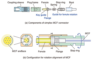
To achieve precise rotational angle alignment for the MCF, we have studied a simplex MCF connector that enables us to adjust the rotational angle of the ferrule when assembling the connector and to narrow the rotational angle range of the ferrule when connecting the connector. Our MCF connector components are shown in Fig. 2(a). The plug frame, flange, and stop ring are unique to the MCF connector. The other parts are the same as those used in the conventional SC connector. The plug frame has two key guides. The stop ring has guides to rotate the ferrule, and these guides fit the key guide. A schematic diagram of the rotation structure is shown in Fig. 2(b). As the stop ring rotates around the plug frame, the ferrule housing the MCF also rotates along with the stop ring. In this configuration, the rotational angle can be aligned precisely by monitoring the MCF facet with a microscope after the MCF is fixed to the ferrule. Then the stop ring is fixed to the plug housing with an adhesive at an optimum angle.
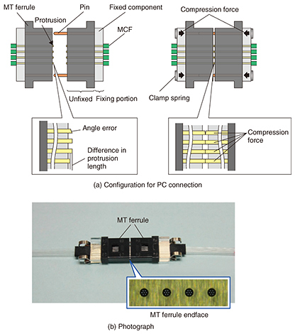
We tested the repeatability of the connection loss for the MCF connector using 7-core MCF with a core pitch of 50 μm. The variation between maximum and minimum losses was about 0.1 dB. This result indicates that the MCF connector suppresses the variation of the rotation angle to less than 1.1 degrees. We also measured the connection losses of the fabricated MCF connector at a wavelength of 1.55 μm. The connection loss was sufficiently small at < 0.2 dB with an average value of about 0.1 dB. We confirmed that the measured connection loss values were the same as those of the conventional simplex SCF connector. Simplex SCF connectors such as SC or MU (miniature universal coupling) connectors employ a physical-contact (PC) connection that is in direct contact with the fiber endface, which is done by pressing the ferrule with the polished convex spherical end. The PC connection obtains high return loss by reducing Fresnel reflection at the connection point and also makes it possible to achieve high-power durability by eliminating organic substances such as adhesive at the connection point. The MCF connector must achieve the PC connection not only at the center core but also at the outside cores. To do this, the MCF connector has a larger contact area between the mated fiber endfaces compared to the SCF connector. For the MCF connector, we clarified the relation between the fiber end shape and the compression force required for the PC connection. We found that the end shape changes in a complex manner when applying the compression force to the ferrule and MCF simultaneously. We established the design method for the PC connection of MCF using a finite element method simulation with a three-dimensional asymmetric geometry model that conforms to the actual endface structure [1]. We have designed and fabricated 7-core MCF connectors using our design method. All the cores of the fabricated MCF connectors provided a high return loss of more than 45 dB, which verifies the PC connection. 3. Multiple MCF connectorThe MCF enables us to increase the core density of a fiber cable in a long-haul transmission or to reduce the number of fibers in a datacenter optical link. To construct such a system using the MCFs, we need optical connectors for both single and multiple MCFs. The conventional multiple SCF connector achieves the multi-fiber connection by coupling the mechanically transferable (MT) ferrule accommodating the multi-fiber array with two guide pins. The multiple MCF connector also employs the MT ferrule in order to obtain the same performance and operability as the conventional multiple SCF connector. The basic structure of our devised multiple MCF connector is shown in Fig. 3(a). The configuration that mates the MT ferrules using the two pins is the same as that of the conventional MT connector. The conventional MT connector fixes the fibers to the micro-hole of the MT ferrule with adhesive. Our multiple MCF connector separates the fixed portion of the fibers from the MT ferrule. That is, the fibers are fixed at the fixing component rather than at the ferrule. We devised the new configuration for PC connection of multiple MCFs. However, the difference in the protrusion length of the MCFs from the MT ferrule and the angle error of the polished fiber end make it difficult to achieve PC connection of multiple MCFs. We found that the PC connection of the MCF array could be achieved by using the elastic compression force of a fiber at the unfixed portion generated when the mated MCFs are pressed together [2]. A photograph of the fabricated quadruple-MCF connector for 7-core MCF is shown in Fig. 3(b). On the MT ferrule endface, the cores of the four MCFs are aligned to have the same arrangement. The average insertion loss of the fabricated connectors was less than 0.3 dB. The result indicates that our multiple MCF connector has the same insertion loss as the multiple SCF connector. The return losses exceeded 45 dB, which confirmed that all the connection points achieved PC connections.
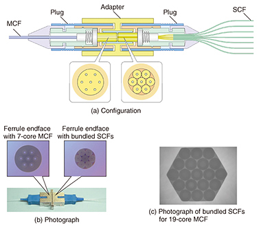
4. FI/FOA FI/FO device that couples each core of the MCF optically with individual SCFs is essential to construct a transmission system that uses MCF. The NTT laboratories have studied a bundled fiber FI/FO device that realizes a closely packed core arrangement of an MCF by utilizing individual SCFs. The bundled fiber FI/FO device enables us to achieve a pluggable connection by accommodating the bundled fibers in connector housings. The basic configuration of the FI/FO device is shown in Fig. 4. It employs two ferrules and a split sleeve. The MCF is inserted into the micro-hole of one of the ferrules. The SCFs required for the MCF core arrangement are inserted into the micro-hole of the other ferrule. The inserted SCFs are then fixed in place with adhesive. The portion of the SCFs inserted into the ferrule has the same cladding diameter as the core pitch of the MCF. The core arrangement of the bundled fibers at the ferrule end is made to correspond to the hexagonal closely packed core arrangement of the MCF by inserting individual SCFs into the circular hole, as shown in Fig. 4(b). Because the FI/FO device utilizes the same plug and adapter as the simplex MCF connector, the rotation of the ferrule via the stop ring enables us to match the core arrangement of the MCF and SCFs.
The insertion loss measured using the fabricated FI/FO device for 7-core MCF was sufficiently small at less than 0.3 dB, with an average value of 0.12 dB. The return losses exceeded 45 dB, which confirmed that all the connection points achieved PC connections. With the configuration of the FI/FO device as shown in Fig. 4(a), we can change the sectional shape of the ferrule hole to a hexagon (Fig. 4(c)) or a square to achieve a FI/FO device that corresponds to various types of MCF with different numbers of cores and core arrangements from those of the 7-core MCF. 5. Future prospectsIn this article, we described connection technology that includes a simplex connector, multiple connector, and FI/FO device for MCF, which is expected to be the transmission medium in future high-capacity transmission systems. R&D on MCF connection technology is steadily progressing and will enable us to achieve the same performance as the connection technology for SCF. Meanwhile, further efforts are necessary to achieve the reliability and mass production required for practical use of MCF connection technology. We will continue to promote R&D for future ultra-high-capacity transmission systems. References
|
|||||