 |
|||||||
|
|
|||||||
|
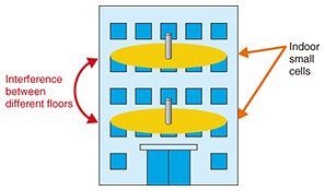
Regular Articles Vol. 15, No. 7, pp. 41–44, July 2017. https://doi.org/10.53829/ntr201707ra2 Path Loss Model to Evaluate Interference for Small Cells between Different FloorsAbstractNTT Access Network Service Systems Laboratories and NTT DOCOMO have been carrying out joint research and development (R&D) toward construction of the fifth-generation mobile communications system (5G). This article presents a path loss model developed as one of our R&D activities. Keywords: propagation, 5G, high frequency band 1. IntroductionNTT Access Network Service Systems Laboratories and NTT DOCOMO have been conducting a joint study toward development of the fifth-generation mobile communications system (5G). The results of measurements carried out jointly made it possible to clarify the path loss characteristics of the indoor environment in the high frequency band. This article presents the developed path loss model. 2. Path loss modelFrequency allocation of 5G, particularly the high frequency bands above 6 GHz, will be discussed at the World Radiocommunication Conference to be held in 2019. To discuss the appropriate frequency allocation, it is important to evaluate the interference between 5G systems and other existing systems. In the interference evaluation, it is necessary to understand the path loss (attenuation of the radio wave) in order to understand the interference power. Path loss varies depending on the frequency, so it is essential to construct a path loss model in the frequency band that will be used. It is assumed that the high frequency band above 6 GHz will be used for 5G, and therefore, the standardization group 3rd Generation Partnership Project (3GPP) is standardizing the path loss models of the high frequency band [1]. In 3GPP, office environments are assumed as the indoor small cell scenarios, but the path loss model that can be used in that environment is only for a single floor (the same floor). In order to accurately evaluate interference, an evaluation of inter-floor interference [2] is also required (Fig. 1). NTT Access Network Service Systems Laboratories has developed a path loss model for evaluating inter-floor interference for a wide range of frequencies as part of efforts to realize various wireless communication systems.
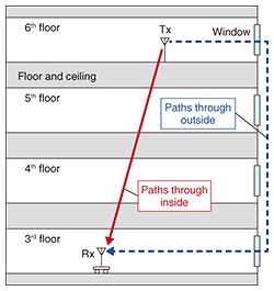
3. Prediction results produced with developed path loss modelTo understand the inter-floor interference of indoor small cells in an office environment, we measured path loss using five frequency bands (0.8, 2.2, 4.7, 26.4, and 37.1 GHz), including the bands above 6 GHz in a multistory building of NTT DOCOMO (from the third to sixth floors). As a result, we clarified that the path loss characteristics between different floors were represented by two dominant propagation paths inside and outside the building in a wide frequency band (Fig. 2). Here, the propagation path inside the building is the path transmitted through the floors (and ceilings) between the transmitter (Tx) and the receiver (Rx). The propagation path outside the building is the path that is diffracted at the window frame of the Tx floor, propagated outside the building, which then re-enters from the window of the Rx floor. The propagation path inside the building attenuates due to transmission loss caused by ceilings and floors, and the propagation path outside the building attenuates because of the diffraction loss at the window.
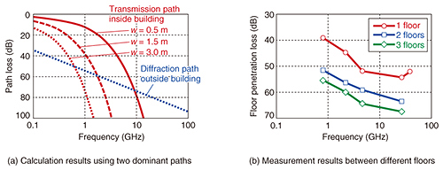
The results of calculating the path loss using the proposed model for these two dominant paths are shown in Fig. 3(a), and the results of measuring the path loss between different floors are shown in Fig. 3(b). The measurement results show the median values of path loss at each floor. The value is normalized by the path loss when the Tx and Rx are set on the same floor, and it therefore represents the floor penetration loss when the Tx and Rx are on different floors.
The calculation results in Fig. 3(a) show the path loss of the path inside the building transmitted through floors when varying the floor thickness w, and that of the path outside the building that is diffracted at the window frame. The path losses are calculated from 0.1 GHz to 100 GHz. In the measurement environment, the thickness of the floor material was 1.5 m per floor. It can be seen that the transmission loss increases rapidly as the floor thickness increases (that is, as the distance between floors increases) or as the frequency increases. In contrast, the diffraction loss of the path outside the building increases gently with respect to the frequency increase. Therefore, when the frequency is low or the distance between floors is small, the path inside the building (transmission path) becomes dominant, and when the frequency is high or the distance between floors is large, the path outside the building (diffraction path) becomes dominant. The frequency dependence of the measurement results in Fig. 3(b) can be explained by using the two dominant paths. The path loss for a distance consisting of one floor level increases sharply as the frequency increases up to 4.7 GHz, but over 4.7 GHz the path loss increases gently. Also, in the case of two or three floors, the path loss increases gently with respect to the frequency increase. It is thought that the path inside the building (transmission path) is dominant up to 4.7 GHz at a distance of one floor level (e.g., the distance between the fifth floor and the sixth floor), and the path outside the building (diffraction path) is dominant under the other conditions. As discussed above, when the two dominant paths are used, it is possible to express the path loss characteristics in a wide frequency band. From this result, for example, when base stations for indoor small cells are installed near a window, it is necessary to pay attention to the fact that interference between floors becomes especially large. 4. Future overviewThis article presented a developed path loss model that can represent the path loss characteristics between different floors. The proposed model is suitable for evaluating inter-floor interference of indoor small cells. We expect that the model will be utilized for 5G, which is a key topic in the research, development, and standardization in the wireless communication field worldwide. A paper describing the proposed model won the Best Paper Award at the 2016 International Symposium on Antennas and Propagation (ISAP 2016). Please refer to the paper [3] for more detailed results. In order to contribute to the construction of various wireless communication systems, we intend to actively engage in the modeling of propagation phenomena for a wider range of frequencies and environments. References
|
|||||||


