 |
|||||||||||||
|
|
|||||||||||||
|
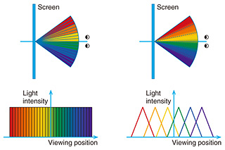
Feature Articles: Creating Immersive UX Services for Beyond 2020 Vol. 15, No. 12, pp. 32–36, Dec. 2017. https://doi.org/10.53829/ntr201712fa6 Smooth Motion Parallax Glassless 3D Screen System that Uses Few ProjectorsAbstractWe propose a glassless 3D (three-dimensional) screen system that enables natural stereoscopic viewing with motion parallax in a wide viewing area. The use of a spatially imaged iris plane screen and linear blending technology makes it possible to use fewer image sources and projectors than existing multi-view projection systems. Keywords: glassless 3D, optical linear blending, motion parallax 1. IntroductionA number of methods have been proposed for glassless three-dimensional (3D) displays that include motion parallax. One method, for example, involves projecting images from multiple directions onto a special screen having a narrow diffusion angle to create a multi-view image (Fig. 1(a)). Natural 3D vision can be achieved with this method with only a slight decrease in resolution [1, 2]. Jones et al. [2] proposed the use of this method to achieve a natural 3D vision system including motion parallax in a 135-degree viewing range by arranging 216 projectors at 0.625-degree intervals. This system can project images of people with high presence as if they were actually in that location. However, in systems like this using many projectors, several things are necessary in order to switch viewpoints smoothly. These include creating many multi-view video sources, preparing the large number of projectors, and synchronizing the video sources. NTT Service Evolution Laboratories has been working to address these needs by focusing on optical linear blending technology that smoothly blends the luminance ratio of multiple images as the viewpoint moves (Fig. 1(b)). This is a glassless 3D screen system enabling smooth movement of viewpoints using very few projectors. In our earlier implementation [3], we found that it was difficult to increase the display area and widen the viewing area as a result of the optical configuration of the lens system.
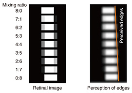
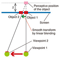
In this article, we propose an improved multi-viewpoint glassless 3D display system that overcomes previous display and viewing area problems by using a special optical screen called a spatially imaged iris plane screen developed in collaboration with Tohoku University [4, 5]. 2. Glassless 3D display screen adapted for viewpoint movementIn this section, we describe the optical linear blending technology and the spatially imaged iris plane screen. 2.1 Optical linear blending technologyChanging the luminance ratio of two overlapped objects separated by a fusion limit enables the position of an object perceived by a person to change smoothly between the two objects (Fig. 2). Utilizing this phenomenon makes it possible to present depth using motion parallax and binocular disparity. For example, let us assume a system such as that shown in Fig. 3, in which the luminance of Object 1 gradually decreases as the viewpoint moves from Viewpoint 1 to Viewpoint 2 and the luminance of Object 2 gradually increases. In this system, the person perceives that the object is at the position of depth S due to the motion parallax.
This principle enables the intermediate viewpoint between the two viewpoints to be continuously interpolated and enables smooth viewpoint switching in the motion parallax even with a small number of projectors. We verified this principle earlier with a prototype based on conventional optical lenses and thus demonstrated the viability of a natural glassless 3D display harnessing both motion parallax and binocular parallax [3]. The only problem with the earlier prototype is that we were unable to easily increase the size of the display area or widen the viewing area due to physical constraints of the optical lens system. 2.2 Spatially imaged iris plane screenWe developed a spatially imaged iris plane screen that presents an image of the iris plane of the projector in the air. This screen consists of a reflective layer, a UV (ultraviolet) polymerized Fresnel lens layer, and an anisotropic diffusion layer, as shown in Fig. 4. This screen forms an iris plane at position d that satisfies 1 / f = 1 / a + 1 / d, assuming that the projection distance on the front surface of the screen is a and the focal length of the Fresnel lens is f.
When the iris plane of the projector is sufficiently small, the luminance distribution around the line of the projection plane can be controlled by the characteristics of the anisotropic diffusion layer. When the diffusion characteristics are narrowed, the light from the projector gathers in a narrow range. Therefore, it is considered that the smooth luminance distribution characteristics accompanying the movement of the viewpoint necessary for linear blending can be achieved. In addition, this screen is thin and flexible, and because it is a front projection type, it can easily be installed in a smaller space than that required for the conventional rear projection type. We made a 50-inch prototype of the spatially imaged iris plane screen and conducted experiments to measure the luminance distribution and to project multi-viewpoint images. 3. Experimental assessmentWe report here the results of the above experiments. 3.1 Luminance distribution on the new optical screenWe measured the luminance distribution of the iris plane imaged by the optical screen. The luminance distribution characteristics of the iris plane for a single projector are shown in Fig. 5(a). One can see that as a result of the anisotropic diffusion layer with large diffusion only in the vertical direction, luminance is only uniformly spread in the vertical direction, while diffusion in the lateral direction is Gaussian. The slope reveals a linear luminance change as the luminance gradually decreases as it moves away from the center of the projection plane. We measured how five iris planes overlapped in the region of half-value luminosity when five projectors were deployed. The luminance distribution of the spatially imaged iris plane for three projectors is shown in Fig. 5(b), and the luminance distribution of the iris plane for five projectors is shown in Fig. 5(c). One can see that when images are projected from multiple projectors, linear blending works properly in accordance with the luminance ratio, and iris plane luminance from multiple overlapping projectors becomes constant.
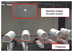
3.2 Prototype system and projection evaluationWe set up a multi-view image projection system with five projectors (Fig. 6) and then evaluated projected images using the prototype. Photographs taken of the center of the iris plane from five viewpoints and four mid-points between the viewpoints are shown in Fig. 7. It can be seen from these photographs that different images are observed depending on the position of the viewpoint, and that the intermediate viewpoint is also interpolated. Therefore, we confirmed that the spatially imaged iris plane screen provides natural stereoscopic viewing with motion parallax.
3.3 DiscussionWe explain here how we evaluated the relationship between projector spacing and reproducible depth in the proposed system. Let A be the fusion limit angle, d the distance between the screen and the iris plane, S the perceived depth distance, and t the interval between the centers of the iris plane. Depth S is calculated by the interval t between the viewpoints as follows: S = (d * ν) / (t – ν) v = d * tan (A)(1) S’ = d * ν / (t + ν)(2) 4. Future workWe successfully developed a glassless 3D display screen adapted to viewpoint movement that dramatically reduces the number of required projectors. We demonstrated through assessment of projections that with our approach, we can effectively slash the number of projectors from one-third to one-tenth the number required in the conventional glassless 3D scheme accompanied by motion parallax using multi-view images. The fact that our screen uses only a few video sources and does not require software processing since it is under optical luminance control makes it especially attractive for remote communications applications and for live broadcasts requiring real-time processing. Moreover, as a Fresnel lens-based light-concentrating device, the screen can also be implemented as a very thin ultrahigh luminance front projection screen. This makes it highly portable, easy to install and set up, and ideal for outdoor 3D signage and a wide range of other potential applications. References
|
|||||||||||||


