|
|||||||||||||
|
|
|||||||||||||
|
Feature Articles: Research and Development of Life-cycle Maintenance of Telecommunication Infrastructure Vol. 16, No. 1, pp. 19–25, Jan. 2018. https://doi.org/10.53829/ntr201801fa2 Automatic Deterioration Evaluation Technique to Improve the Efficiency of Manhole InspectionAbstractWe have developed a non-entry manhole inspection technique with a function for automatic deterioration judgment. This enables workers to operate safely without having to enter manholes and can eliminate the need to drain manholes, substantially reducing the inspection workload. This technique not only improves the safety and efficiency of manhole inspections but also yields high-resolution inspection images that can be used to accurately predict the deterioration of facilities. It can therefore play an important role in improving the maintenance cycle. Keywords: manholes, non-entry inspection, automatic deterioration evaluation  1. IntroductionTelecommunication and civil engineering facilities such as ducts and manholes are mostly buried under roads, where they are subjected to external forces such as soil pressure, groundwater pressure, and the loads exerted by passing vehicles. Over time, this can lead to degradation of the facilities such as corrosion, deformation, and cracks in concrete structures. This degradation can lead to various problems, including not only interruption of telecommunication services but also the collapse of roads. It is therefore important to inspect these facilities in a timely manner so that appropriate repair/reinforcement or renewal measures (maintenance planning/repair and reinforcement) can be implemented. Much of the telecommunication infrastructure in Japan was constructed over thirty years ago, and trends such as long-term deterioration of facilities and reductions in the number of skilled workers make it important to ensure that the abovementioned maintenance cycle (inspection, maintenance planning, and repairs/reinforcement) of the enormous number of equipment facilities is made more efficient. For this sort of maintenance cycle, we are promoting at NTT Access Network Service Systems Laboratories research and development aimed at achieving fundamental reforms (operational innovation) in operation and maintenance work. 2. Importance of inspection technologyImplementing a maintenance cycle efficiently requires technologies for preferentially inspecting and preserving equipment that has already deteriorated, as well as techniques for preventing deterioration. The degree of deterioration in facilities is greatly influenced by the installation environment, so it is important to ascertain, examine, and model the effects of this environment. It is also necessary to prioritize conservation efforts by predicting deterioration based on time-series analysis of the state of degradation. The inspection results are traditionally recorded in a form such as text input or sketches that are difficult to analyze as a temporal series, making it impossible to model or predict deterioration with sufficient accuracy. However, obtaining and storing the inspection results in the form of high resolution images may make it possible to solve these issues. With high resolution images, image processing techniques can be used to determine the amount of deterioration automatically, and the resulting data can also be used for time-series analysis because it is possible to gather information about how the degradation is progressing. This problem has a strong affinity to deep learning,*1 which is evolving rapidly, and is expected to lead to innovative deterioration analysis tools through the use of advanced next-generation image processing technology. Thus, in developing techniques aimed at revolutionizing the maintenance cycle of such facilities, it is vital to develop techniques that not only ascertain the current state of deterioration but also provide data that can be used to model and make future predictions about this deterioration.
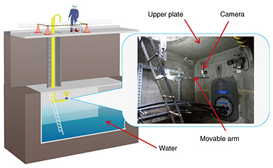
3. Difficulties in manhole inspectionNTT is responsible for approximately 680 thousand manholes nationwide. Currently, these manholes are mostly inspected by having workers enter the manholes to perform a visual inspection and record the state of deterioration. However, these inspections involve dangers including the risk of falls and a lack of oxygen. Also, since most of the manholes have accumulated water, it is necessary to drain the accumulated water from the manhole with a pump before entering it, and this greatly increases the time and cost of inspections. At NTT Access Network Service Systems Laboratories, we have developed a non-entry manhole inspection technique aimed at resolving these problems and using image processing to enhance the quality of inspections. 4. Non-entry manhole inspection techniqueLong-term deterioration of manholes is caused by corrosion of reinforcing bars inside the concrete. As the corrosion proceeds, the reinforcing bars eventually become exposed. This corrosion reduces the cross-sectional area of the reinforcing bars and reduces the manhole’s strength. We confirmed from the results of previous research done by NTT Access Network Service Systems Laboratories that the sign of reduced strength in NTT’s standard manholes tends to be manifested more clearly in the upper plates of these structures [1, 2]. We therefore focused on the upper plates where deterioration such as exposed reinforcing bars is likely to occur and developed an inspection technique in which a camera mounted on a movable arm is used to capture images of the upper plate, and the state of deterioration is automatically judged from these images. The apparatus consists of a movable arm equipped with a camera that is inserted through the manhole opening on the ground. The camera then takes pictures of the upper plate of the manhole interior. We used a structure whereby an L-shaped guide is provided so that the camera can move parallel with the upper plate. By using a camera with a wide-angle lens, we can take pictures over the entire length of the upper plate as long as a distance of 50 cm can be maintained between the upper plate and the camera (Fig. 1). The upper plate is photographed at fixed intervals while moving the camera, and then image processing is carried out to stitch these photographs together and automatically evaluate the state of deterioration. With this technique, since the movable arm moves to a position 50 cm away from the upper plate, in most cases there is no need to drain the interior of the manhole. This speeds up the inspection work and reduces the cost.
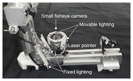
5. Automatic upper plate imaging deviceA manhole must be repaired when there is pronounced deterioration involving exposed reinforcing bars and peeling concrete, which can be detected from the results of stitching together images of the upper plate. To ensure that the images are of sufficient quality for detecting deterioration, two types of lighting are provided: fixed lighting and movable lighting. Direct light from the fixed lighting and indirect light from the movable lighting can be used together to provide uniform illumination of the manhole upper plate (Fig. 2). Furthermore, when the photographs are processed, a laser pointer mounted next to the camera makes it possible to correct variations in the camera range and orientation by detecting the spot of light produced by this pointer (Fig. 2).
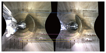
In the image stitching process and automatic deterioration judgment, it is preferable that the series of images are of uniform quality. If the camera is kept at a fixed distance and orientation with respect to the upper plate, then each pixel will have the same length and information content. However, in a large manhole, the arm must be extended up to 2.5 m. With such a large extension, the arm can sag due to the weight of the arm material and the clearance between adjacent parts of the arm. This would necessitate some sort of mechanism to suppress sagging when the movable arm is extended. However, by making improvements including reducing the weight of the camera arm, optimizing its shape, and inserting spacers at its connection points, we were able to suppress the amount of sagging at the tip of the L-shaped guide to within 5 cm vertically. 6. Upper plate image stitchingImage stitching is necessary in order to obtain a single image of the upper plate, but first the variations in the distance between the upper plate and the camera and the viewing angle between each individual photo due to deflection of the camera arm must be corrected. This was done by using light spot detection as discussed above. Light spot detection is an image analysis technique that detects and acquires coordinates of red laser light emitted from the device [3]. After the photographs captured at fixed intervals were corrected by light spot detection, we used AKAZE feature quantities (OpenCV 3.0.0 library) to detect the locations in each neighboring image with matching features, and we stitched the images together by superimposing these points (Fig. 3). By repeating this operation, we ended up with a single upper plate image.
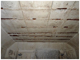
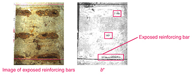
7. Deterioration evaluation techniqueThe color of each deteriorated location (such as exposed reinforcing bars) differs significantly from that of the concrete surface (Fig. 4), but the large number of false positives caused by surface dirt or surface patterns leads to practical difficulties when attempting to detect deteriorated locations based on color information alone. We therefore improved the detection accuracy by concentrating on the fact that the reinforcing bars are linear, and combining color-based detection with the detection of shapes with linear characteristics corresponding to the reinforcing bar width.
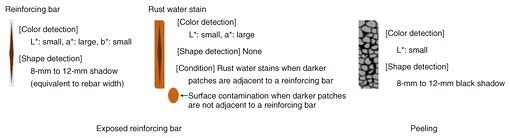
7.1 Color detectionSince the brightness and hue of the photos vary depending on the imaging environment inside the manhole, a threshold value for the detection of deteriorated parts was set based on the color of an area of sound concrete when performing color detection. The color of sound concrete is defined as the color that occupies the largest area in an image with reduced colors. To distinguish between rust water stains and reinforcing bars, we converted the image into the L*a*b* color space*2 for processing. In the L*a*b* color space, it is possible to distinguish between rust water stains and reinforcing bars in the b* (blue-yellow) channel, as shown in Fig. 5. With the ability to distinguish between rust water stains and reinforcing bars in this way, it is possible to classify darker patches as rust water stains when they are adjacent to a reinforcing bar and as surface contamination when they are not adjacent to a reinforcing bar, as shown in Fig. 6.
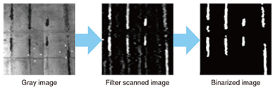
To extract these corresponding regions at each site of deterioration (exposed reinforcing bars, rust water stains, or peeling), we set a threshold value t as shown in Eq. 1 to distinguish these regions from the color of a sound concrete surface (L*N, a*N, b*N). tN, M = αN, M N + βN, M(1) Here, N = L*N, a*N, b*N, M = {rebar/stain/peel}. The L*a*b* color space image is binarized*3 using the derived threshold value, and candidate regions for each type of deterioration are obtained by evaluating the following logical products. Reinforcing bar F = BL*, rebar & Ba*, rebar & Bb*, rebar Rust water stain R = BL*, stain & Ba*, stain Peeling S = BL*, peel & not(Ba*, stain) B is a binarized image obtained by applying each set threshold value. 7.2 Shape detectionFor shape detection, we used information about the width of the reinforcing bars. The reinforcing bars inside manholes are generally 8–12 mm in diameter. The number of pixels occupied by the width of a reinforcing bar can be calculated from the light point coordinates of the laser pointer as described above. This enabled us to detect reinforcing bars by scanning the image with a filter having a column width equal to the calculated number of pixels. The results are shown in Fig. 7, where one can see that it is possible to extract linear shapes having the width of reinforcing bars.
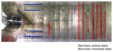
8. Application of technique to inspect manholesIn manhole inspections using this technique, a fixed pedestal is set in place after opening the manhole, and the movable camera arm is fixed to this pedestal. Then a personal computer is used to control the arm extension, photograph the upper plate, stitch the photographs together, and perform automatic deterioration judgment. In the inspection results, as shown in Fig. 8, the exposed reinforcing bar locations are shown as masked out regions, enabling the user to visually judge the state of deterioration. The series of inspection tasks from installing to removing the equipment can be performed by one worker in about 15 minutes (equivalent to the actual inspection time taken for a conventional manhole check). In this technique, however, since the movable arm moves at a position 50 cm away from the upper plate, there is no need to drain the manhole in most cases, which substantially reduces the inspection time compared to the conventional method. Thus, it reduces the amount of labor and the cost compared with conventional inspection. Also, since deterioration is detected automatically from photographic images, this technique is less dependent on worker skill and less likely to overlook degraded parts. Furthermore, it can be used to prioritize maintenance efforts by accumulating data that can be quantitatively evaluated.
9. Future prospectsTo thoroughly reform our facilities maintenance cycle, we have developed a non-entry manhole inspection technique with a function for automatic deterioration judgment. This technique makes it possible to carry out manhole inspection work more safely since there is no need for workers to enter the manhole. Also, since it is possible to eliminate almost all of the drainage work that has hitherto been necessary, this technique can greatly reduce the time taken for manhole inspections and can increase the efficiency of inspection work. Furthermore, since the state of deterioration is automatically judged from high resolution images, it is possible to prevent problems from being overlooked. This means that a high inspection quality can be guaranteed without having to rely on the skills of the worker performing the inspection. The use of high resolution images in the operation and maintenance of infrastructure facilities yields valuable information for increasing the precision of deterioration models and deterioration predictions. Although this current study was focused on improving the efficiency of the maintenance cycle from the viewpoint of inspection technology, NTT Access Network Service Systems Laboratories aims to further increase the efficiency of the maintenance cycle and will continue to promote research and development of all factors relating to inspection, conservation planning, and repair reinforcement. References
|
|||||||||||||