 |
|||||||||||||
|
|
|||||||||||||
|
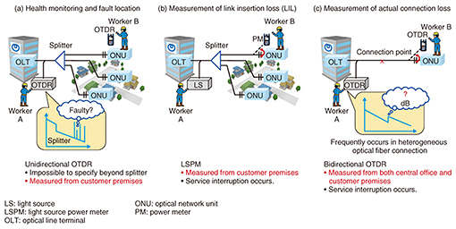
Regular Articles Vol. 16, No. 3, pp. 23–29, Mar. 2018. https://doi.org/10.53829/ntr201803ra1 Branched Optical Fiber Loss Measurement Technology for End-to-end Testing in Optical Access NetworksAbstractWe have developed branched optical fiber loss measurement technology that enables us to measure branched fiber sections beyond optical splitters from a central office without entering the customer’s premises. This article provides an overview of the developed technology and its application to the operation and maintenance of optical access networks. Keywords: optical access, fiber loss, PON 1. Optical fiber measurement for optical access network maintenanceThe number of fiber-to-the-home (FTTH) subscribers has reached approximately 29.30 million in Japan, about two-thirds of which—20.05 million—are with NTT EAST and NTT WEST. It is therefore important to reduce the cost of operating the huge amount of optical fiber that this system employs and ensure quality over a long period of time. Passive optical networks (PONs) have been adopted for the majority of optical access networks. A PON has a topology where multiple customers share optical fibers using an optical splitter. PONs have contributed to achieving economic optical fiber network construction. On the other hand, they have also caused complications regarding the operation and maintenance of optical fiber equipment outside the central office, especially maintenance work involving the use of optical techniques for monitoring, testing, and identifying fibers. Specifically, the optical signal used for maintenance and launched from a central office is equally divided by an optical splitter, so it is necessary to work from the customer side as well. Optical time domain reflectometry (OTDR) [1] is used for monitoring optical access networks from the central office side. However, since all backward scattered light beyond the splitter overlaps, it is impossible to perform the health monitoring and fault location in a section of branched optical fiber (Fig. 1(a)). In this case, measurement equipment is installed at the customer’s premises to measure branched optical fiber sections, and the maintenance work requires the customer’s presence. Moreover, redundant staff may be dispatched depending on the cause of the failure. Additionally, there are similar cases when evaluating the link insertion loss (LIL) from the central office to the customer’s premises, which is the most important characteristic of optical access networks, and the connection loss of the optical fiber. Similarly, when using a standard method to measure light such as the light source power meter (LSPM) [2] method or the bidirectional OTDR [3] method, it is necessary to measure from both the central office and the customer’s premises (Figs. 1(b) and (c)). To evaluate fiber quality after an investigation and fault repair, these measurements can be easily conducted when the customer is not present, such as during construction. However, measurements are difficult to perform when customers must be provided with certain services, for example, PON services.
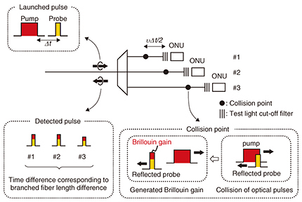
Therefore, we have worked on developing a new optical loss measurement technology focusing on the characteristics of optical access networks, where one end of the optical fiber is located at the customer’s residence, and where an optical splitter is installed. 2. Branched optical fiber loss measurement techniqueA schematic diagram of our branched optical fiber loss measurement technique is shown in Fig. 2 [4]. This technique involves using the differences in length between branched fibers resulting from construction and end reflections at a common test light cut-off filter [3] installed in front of an optical network unit (ONU) to measure existing optical access networks without any additional optical devices. Two optical pulses are launched into the fiber under test (FUT) with a time difference Δt and an optical frequency difference Δf. The light pulses have lower and higher optical frequencies and are respectively called the probe and pump pulses.
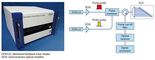
The probe pulse is reflected at the far end, and collides with the pump light at a position corresponding to the time difference Δt, Then a Brillouin interaction occurs. In this Brillouin interaction, the probe pulse is amplified by the pump pulse. The generated Brillouin gain corresponds to the loss experienced by the pump light until the collision position; therefore, Brillouin gain analysis can be used to measure the optical loss. The probe pulse that obtained the Brillouin gain returns to the incident side with a time difference corresponding to the branched optical fiber length difference. Therefore, it is possible to acquire the optical loss data for each branched optical fiber by analyzing the Brillouin gain for each pulse. Note that it is necessary to set the probe pulse so that it is narrower than the time difference caused by the branched optical fiber length difference. In addition, it is possible to acquire the loss distribution data by changing the time difference Δt. We describe here the remote and single-end measurement of the LIL [5] and connection loss [6] using the branched optical fiber loss measurement technique. The LIL is obtained by subtracting the far-end return loss from the loss that the pulse experienced in the round-trip. The round-trip insertion loss of the probe pulse is measured without a pump pulse. The far-end return loss is obtained with the gain difference given immediately in front of the reflector by changing the launch order of the probe and pump pulses. Therefore, this technique can be used to conduct a remote LIL measurement for each customer. The connection loss can be measured by changing both the time difference Δt and the launch order of the probe/pump pulse. When we launch the pump after the probe, we can obtain the loss distribution from the input end, and when we launch the probe after the pump, we can obtain the pseudo loss distribution from the far end. Therefore, bidirectional measurement can be achieved from a single end. 3. Developed apparatus of branched optical fiber loss measurementA photograph and the configuration of the measurement system we developed are shown in Fig. 3. Two DFB-LDs (distributed feedback laser diodes) were used as probe/pump sources, whose frequency difference was set at a Brillouin frequency shift of about 10 GHz. The probe/pump lights were launched into an FUT after being amplified and pulsed by SOAs (semiconductor optical amplifiers) 1 and 2. The reflected probe pulses from the FUT were detected at the PD (photodetector) after removing the pump light with an optical filter. This is the first technique capable of measuring optical loss using Brillouin phenomena, and it is the only technique that can measure the loss distribution beyond an optical splitter.
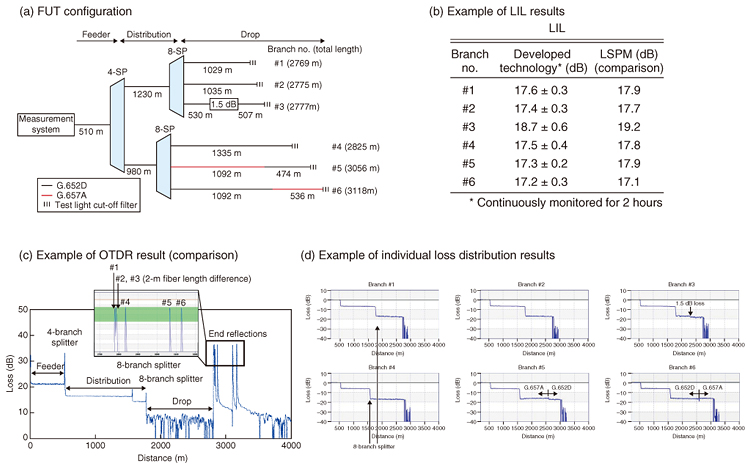
4. Measurement examples with branched fiber loss measurement apparatusIn this section, we describe some examples of measurements obtained with our branched fiber loss measurement apparatus. The measurement results for branched optical fibers obtained with the developed measurement apparatus and conventional LSPM and OTDR are shown in Fig. 4. The FUT, which was composed of six fibers of different lengths, is depicted in Fig. 4(a). The LIL results obtained with LSPM and the developed apparatus are in Fig. 4(b). It can be seen that the result with the technique developed for single-end measurement agrees well with the result measured using LSPM. The results obtained with unidirectional OTDR and the developed apparatus are presented in Figs. 4(c) and (d). They show that the loss distribution of branched fiber sections cannot be measured with unidirectional OTDR. In contrast, it can be seen that the developed apparatus can measure individual loss distributions including loss events.
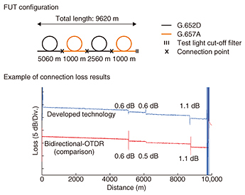
The connection loss results obtained with bidirectional OTDR and the developed apparatus are shown in Fig. 5. The FUT was composed of optical fibers with different bending characteristics (G.652D and G.657A). The results obtained with the developed apparatus for single-end measurement agree well with those obtained with bidirectional OTDR.
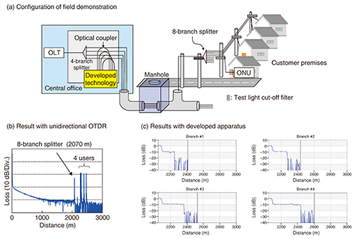
5. Field demonstrationThe configuration and measurement results for a field demonstration using the developed apparatus are shown in Fig. 6. A 4-branch splitter was installed inside a central office, and an 8-branch splitter was installed in a distribution area near four customers’ premises. FBG (fiber Bragg grating)-based reflectors with a nominal return loss of 1 dB at 1650 nm were installed just in front of an ONU. The total length of the test optical distribution network (ODN) was about 2.5 km. We performed the measurement from a test coupler installed immediately below the 4-branch splitter.
Measurement results obtained for a deployed ODN with OTDR and the developed apparatus are shown in Figs. 6(b) and (c). The branched fiber sections were successfully visualized with the developed apparatus in the field. An OTDR trace of the entire ODN is shown in the graph in Fig. 6(b). An 8-branch splitter was installed at 2070 m, and there were four end reflections on the customers’ premises. Enlarged traces of the drop fiber section beyond the 8-branch splitter, which were measured with the proposed system, are in Fig. 6(c). The branched fiber sections were successfully visualized. As mentioned above, the developed apparatus can measure the individual loss distribution for each customer even if the OTDR cannot do so because of overlaps from the branched fiber section or because of the excessive loss of the splitter. 6. Future perspectivesWe introduced branched optical fiber loss measurement technology that enables end-to-end measurement of optical access networks. Since this technology uses end reflection, there are conditions that cannot be measured depending on the optical access networks, such as when they are completely disconnected, when there is a large loss near the far end, and when there is no branch fiber length difference. Nevertheless, we believe that a centralized approach, which is a unique and attractive feature of the developed technology, would result in operational applications that overcome the lack of fiber-end accessibility. The developed technology was commercialized in 2017. We now plan to start employing it as a troubleshooting tool where we require a detailed diagnosis of optical access networks. References
|
|||||||||||||

