1. Introduction
The data transfer speed between communication equipment has been increasing in communication facilities such as datacenters. Therefore, the use of multi-fiber optical links as opposed to single-fiber optical links is expanding in high speed communication links. Multi-fiber push-on (MPO) connectors, a type of optical connector developed by NTT, are most widely used as the interfaces of multi-fiber optical links in buildings. An example of the standard wiring of a datacenter is shown in Fig. 1 [1]. In modern datacenters, high speed communication links such as 40 Gbit/s or 100 Gbit/s are widely used between the aggregation switches and spine switches, and their link speed continues to increase. Examples of the standard high speed communication links using the MPO connector are listed in Table 1 [2–4]. Because inter-switch communication at a datacenter is expected to be over 100 Gbit/s in communication speed and over 100 m in wiring length, the 12-single-mode fiber MPO connector is expected to be used more and more for high-speed communication optical wiring in buildings.
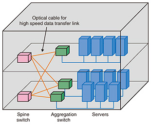
Fig. 1. Example of cabling for datacenter building.
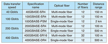
Table 1. Examples of high speed data transfer links using MPO connector interface.
The structure of the MPO connector is shown in Fig. 2. The MPO connector consists of a male plug, which contains pre-inserted guide pins, a female plug with guide pin holes on the connector endface, and an adaptor that couples the plugs with a slide lock mechanism. To connect optical fibers, we have to align the positions of the fiber cores through which signal light passes in order to bring the fiber cores in contact with each other. In the MPO connector plug, the fibers are precisely arrayed and fixed into a mechanically transferable (MT) ferrule, and when one plug is connected to another one, the MT ferrule is aligned with the opposite MT ferrule by using the guide pins and the guide pin holes.
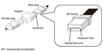
Fig. 2. Structure of MPO connector.
In an actual optical connector connection, it is difficult to perfectly match the positions of the fiber cores, and some of the signal light is consequently lost and not transmitted. This loss (connection loss) affects the communication quality, so it is necessary to evaluate the connection loss. One evaluation method involves using a reference connector. The reference connector should be a highly accurate connector manufactured with less error than the standardized ideal design of an optical connector. This method is widely used because it is accurate based on the standardized design, and it guarantees the interoperability of the optical connectors.
However, there are no reference connectors currently available on the market for the MPO connector, so it is not possible to conduct an accurate evaluation as done for the conventional single-fiber optical connector. Consequently, there may be uncertainty about the measured connection loss between, for example, the manufacturer and the purchaser in the evaluation of the MPO connector. In addition, when the MPO connector is required to have a connection loss equivalent to the conventional single-mode-fiber optical connector, the connection loss of the MPO connector cannot be guaranteed.
We introduce here a high precision 12-single-mode-fiber MPO connector that we developed as a reference connector to achieve accurate evaluation of the 12-single-mode-fiber MPO connector. Our high precision MPO connector is the world’s first 12-fiber MPO connector for single-mode fiber that meets the specifications of the International Electrotechnical Commission (IEC) reference connector.
2. High precision MPO connector
In the connection of optical connectors, any positional error of the fiber core will mainly affect the connection loss, so the target position of the fiber core is specified. However, the actual optical connector may have a deviation between the fiber core position and the target position due to a manufacturing error. The reference connector must therefore be a high precision connector with small error of the fiber core position. For example, the IEC specifies that the connection loss between reference connectors shall be no more than 0.2 dB, which means that the error of the fiber core position should be 0.5 μm or less [5].
There are two difficulties in achieving high precision multi-fiber connectors with a connection loss of 0.2 dB or less. One is the effect of manufacturing error. As mentioned above, in the MPO connector, the fiber cores are aligned by the MT ferrule, but the MT ferrule has a manufacturing error of 0.5 μm at maximum.
The connection loss of the MPO connector calculated based on the manufacturing error of the MT ferrule is given in Fig. 3. The figure shows that the connection loss of the MPO connector given the maximum 0.5-μm manufacturing error of the MT ferrule exceeds the target loss of 0.2 dB. It is difficult to reduce the manufacturing error to less than 0.5 μm with the current manufacturing technology, so in order to achieve a 12-core high precision connector, it is necessary to select connectors with a small manufacturing error from those manufactured with the maximum error of 0.5 μm.
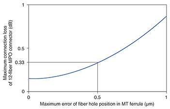
Fig. 3. Calculated connection loss in MPO connector.
The other difficulty lies in measuring the error of the fiber core positions in the MPO connector. In the MPO connector, fiber cores with a diameter of about 10 μm are lined up in a 4.6-mm-wide area. The fiber core position cannot be measured accurately because of the large difference between the observation range and the size of the fiber core to be measured. For this reason, it is not possible to select connectors with a small manufacturing error based on the fiber core position itself.
The procedure for selecting connectors using connection loss when the actual fiber core position is unknown is shown in Fig. 4, and an example of the fiber core position in each procedure is shown in Fig. 5.
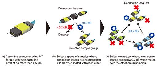
Fig. 4. Selection procedure for high precision MPO connectors.
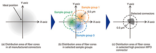
Fig. 5. Example of fiber core position of selected connector samples.
First, we manufacture an MPO connector using an MT ferrule with a manufacturing error of 0.5 μm or less. The fiber core position of the fabricated connector is distributed around the target position, as shown in Fig. 5(a), due to manufacturing error. Next, as shown in Fig. 4(b), we connect the fabricated MPO connectors together and select a sample group exhibiting a connection loss of 0.2 dB or less. Through selection, connectors whose fiber core position is in the range of 0.5 μm are extracted, although the center of the fiber core position will deviate from the ideal position, as shown in Fig. 5(b).
To select connectors with a fiber core position error of less than 0.5 μm from the ideal position, we prepared three sample groups and selected the connectors that had a connection loss of 0.2 dB when they were connected to the connectors of the other sample group. Although the fiber core position of each sample group is unknown, the range where the fiber core can exist can be estimated to determine whether it is 0.5 μm or less based on the fiber core position of the connector selected between each of the sample groups, as shown in Fig. 5(c). We are using this procedure to achieve a high precision MPO connector with a fiber core position of 0.5 μm or less for the first time in the world.
3. Application to MPO connector evaluation
Two widely used optical connector evaluation methods are depicted in Fig. 6. They are used to evaluate the connection losses and other characteristics of the connector. The random mating test method is used when connecting manufactured connectors to each other (Fig. 6(a)). As shown in the figure, the random mating test is not accurate when the fiber core positions have some deviation. Therefore, even if the connection loss was confirmed to be less than a specified value in the random mating test, the connection loss would not always be less than the specified value in actual equipment.
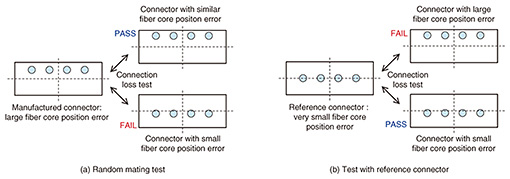
Fig. 6. Example of MPO connector evaluation methods.
In the other method, the manufactured connectors are tested against a reference connector (Fig. 6(b)). Because the reference connector has low deviation of the fiber core position, this method can be performed accurately as shown in the figure, and interoperability between connectors is guaranteed.
However, even high precision reference connectors have a small deviation of the fiber core position. A comparison between the specifications of the reference connector in major optical connector standards and the developed high precision MPO connector is given in Table 2 [5–8]. The developed high precision MPO connector has the same deviation of the fiber core position and connection loss as those of the reference connector for single-mode subscriber connectors (SCs). Since the reference connector for a single-mode SC has been utilized in the practical evaluation of single-mode optical connectors for the last few decades, our developed high precision MPO connector has a sufficiently small deviation for the reference connector for practical connector evaluation.
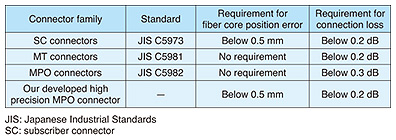
Table 2. Reference connectors in major optical connectors.
4. Summary and future work
We introduced our developed 12-single-mode-fiber high precision MPO connector to realize accurate connector evaluation of the 12-fiber MPO connector. The developed high precision MPO connector is the first in the world to meet the specifications of IEC’s reference connector as a 12-fiber MPO connector for single-mode fibers. The accurate connector evaluation method enables fair competition among connector manufacturers and contributes to the proper procurement of MPO connectors in the NTT Group. We will continue to research a way to achieve a reference connector with more than 12 fibers by focusing on the technological trends of high speed communication.
References
| [1] | TIA-942: “Telecommunications Infrastructure Standards for Data Centers,” Rev. 2, 2017. |
|---|
| [2] | IEEE 802.3bm: “IEEE Standard for Ethernet – Amendment 3: Physical Layer Specifications and Management Parameters for 40 Gb/s and 100 Gb/s Operation over Fiber Optic Cables,” 2015. |
|---|
| [3] | IEEE 802.3bs: “IEEE Standard for Ethernet – Amendment 10: Media Access Control Parameters, Physical Layers, and Management Parameters for 200 Gb/s and 400 Gb/s Operation,” 2017. |
|---|
| [4] | 100G PSM4 MSA: “100G PSM4 Specification,” Ver. 2.0, 2014. |
|---|
| [5] | IEC 61755-2-5: “Fibre optic interconnecting devices and passive components – Connector optical interfaces – Part 2-5: Connection parameters of non-dispersion shifted single-mode physically contacting fibres – Angled for reference connection applications,” Ed.1.0, 2015. |
|---|
| [6] | JIS C5973: “F04 Type connectors for optical fiber cables (Type SC connector),” 2014. |
|---|
| [7] | JIS C5981: “F12 Type connectors for optical fiber ribbons (MT connectors),” 2012. |
|---|
| [8] | JIS C5982: “F13 type connectors for optical fiber ribbons,” 2010. |
|---|
 |
- Ryo Koyama
- Senior Research Engineer, Media Utilization Group, Access Media Project, NTT Access Network Service Systems Laboratories.
He received a B.S. and M.S. in precision engineering from the University of Tokyo in 2001 and 2003. In 2003, he joined NTT Access Network Service Systems Laboratories, where he has been engaged in research on optical fiber wiring and splicing techniques for optical access networks. He is a member of the Institute of Electronics, Information and Communication Engineers (IEICE).
|
|---|
 |
- Chisato Fukai
- Engineer, Media Utilization Group, Access Media Project, NTT Access Network Service Systems Laboratories.
She received a B.E. and M.E. in functional materials science and a Ph.D. in materials science from Saitama University in 1999, 2001, and 2014. In 2001, she joined NTT Access Network Service Systems Laboratories, where she has been researching optical fiber design and related measurement techniques. She is a member of IEICE.
|
|---|
 |
- Yoshiteru Abe
- Senior Research Engineer, Media Utilization Group, Access Media Project, NTT Access Network Service Systems Laboratories.
He received a B.E. in electrical engineering, an M.E. in electronic device engineering, and a Dr. Eng. in electrical engineering from Kyushu University, Fukuoka, in 1996, 1998, and 2005. He joined NTT Opto-electronics Laboratories in 1998. His research interests include optical fiber connectors. He is also acting as Assistant Secretary of SC86B of IEC. He is a member of IEICE.
|
|---|
 |
- Mitsuru Kihara
- Senior Research Engineer, Media Utilization Group, Access Media Project, NTT Access Network Service Systems Laboratories.
He received a B.E. and M.E. in nuclear engineering, and a Dr.Eng. in electronic engineering from Kyushu University, Fukuoka, in 1988, 1990, and 1997. He joined NTT in 1990 and began researching optical fiber interconnection techniques, future network planning, and optical fiber sensing techniques. He is a member of IEICE and the Institute of Electrical and Electronics Engineers (IEEE).
|
|---|
 |
- Kazunori Katayama
- Senior Research Engineer, Supervisor and Group Leader of Media Utilization Group, Access Media Project, NTT Access Network Service Systems Laboratories.
He joined NTT Access Network Service Systems Laboratories in 1997, where he engaged in research of home area networks. Since 2007, he has been engaged in research on an intermediate session control server and optical line switching system and optical fiber cable systems. He is a member of IEICE.
|
|---|

