|
|
|
|
|
|
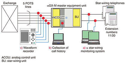
Practical Field Information about Telecommunication Technologies Vol. 17, No. 10, pp. 58–63, Oct. 2019. https://doi.org/10.53829/ntr201910pf1 Introduction to Troubleshooting Cases Related to Telephone Systems in Customer PremisesAbstractIn this article, we introduce two cases involving problems that occurred in telephone systems. In the first case, a connection could not be established even when the customer dialed the correct number. In the second case, silence suddenly occurred during the connection. We investigated and solved these problems using various measurement tools and analysis methods. This is the fifty-fourth article in a series on telecommunication technologies. Keywords: key telephone system, IP phone, PSTN  1. IntroductionThe Network Interface Engineering Group at the Technical Assistance and Support Center provides technical support and on-site troubleshooting for difficult-to-solve problems in Internet protocol (IP) services such as the FLET’S HIKARI NEXT fiber-optic broadband service and public switched telephone network (PSTN) services such as plain old telephone services (POTS). The rapid progression of information and communication technology (ICT) has led to our support of various ICT services. Thus, when we investigate the cause of a problem, we use a variety of measurement methods and equipment. For IP services, we obtain IP packets in a network using packet capture tools, and we analyze those packets using various methods. For PSTN services, we analyze signals using waveform recorders and ISDN (integrated services digital network) protocol analyzers. To inspect key telephone systems, we collect and analyze specific signals in a cable between the master equipment and terminal telephone sets using the α line monitoring system (a tool developed by the Technical Assistance and Support Center). Two recent cases of problems that occurred in customer premises are introduced in this article. 2. Introduction to troubleshooting cases in customer premisesThis section describes in detail the two problems that occurred in customer premises. 2.1 Case 1: Connection cannot be established even if customer dials correct number2.1.1 Overview and investigation methodIn this case, the customer’s key telephone system (αGX-M) was connected to five POTS lines. The customer claimed that a connection could not be established even if the correct number was dialed. On site, the master equipment unit and telephone sets were replaced by service personnel, but the problem persisted. Thus, we conducted an investigation to solve the problem. This consisted of collecting and analyzing data when the problem occurred. The configuration of the measurement setup and tools used in the investigation are shown in Fig. 1. The red circles indicate the measurement points. We investigated the following using several measurement tools. a) Monitoring telephone operation using the α line monitoring system b) Collecting call history using a personal computer, that is, the maintenance console of the system, and checking the call-connection status at the time of the problem c) Checking outgoing-call sequence/selection signals (push button (PB) signals) by monitoring the voltage between the L1-L2 lines using the waveform recorder
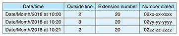
The customer explained that the problem occurred three times during the investigation period. After conducting the investigations above, we analyzed the collected data. The system status at the time the problem occurred is summarized in Table 1.
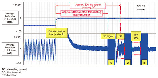
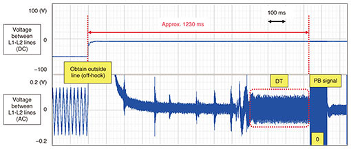
2.1.2 Results of analyzing collected dataa) α line monitoring system When the telephone operation was checked at the time the problem occurred, it was found that the customer was operating the telephone normally by connecting to an outside line using the line key and pressing the dialing buttons corresponding to the destination telephone number. b) Collection of call history via maintenance console When the call history of the master equipment was checked, it was found that the number dialed by the customer on the telephone was recorded; that is, it indicated that the customer was operating the telephone correctly. c) Voltage monitoring between L1-L2 lines by waveform recorder The following information was obtained from the waveform recorder. The waveforms obtained when the problem occurred are shown in Fig. 2.
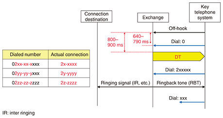
2.1.3 Cause of problem and countermeasureThis problem occurred because the PB signal of the first digit dialed (‘0’) was transmitted from the telephone before receiving the DT from the exchange, preventing that digit from being recognized by the exchange. Furthermore, since the PB signal of the second digit dialed (‘2’) (transmitted after receiving the DT) was processed by the exchange, and given that the first digit of a local office number is ‘2,’ a connection was made to an existing 6-digit local telephone number. The calling sequence is shown in Fig. 3. This problem was solved by changing the initial value of the guard interval before transmitting the first digit of the dialed number from 600 ms to 1000 ms. This can be easily set by using the αGX-M master equipment system data, that is, the 07–47 early dialing prevention timer for making an outside call. The waveforms when setting this value to 1200 ms are shown in Fig. 4.
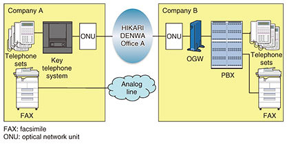
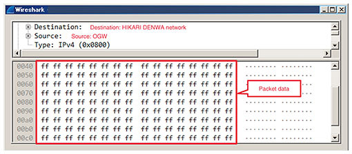
2.2 Case 2: Voice suddenly disappears in connection with specific destination2.2.1 Overview and investigation methodA customer (Company A) was using the NTT HIKARI DENWA IP phone service in its key telephone system. The customer claimed that a voiceless condition occurred during calls with Company B. Company B, meanwhile, was using the NTT HIKARI DENWA (via OGW (Office Gateway) with Primary Rate Interface) in its private branch exchange (PBX). The equipment configuration at both locations is shown in Fig. 5. We captured IP packets using packet-capturing equipment near the ONU (optical network unit) at both locations. Then the data at the time of the problem occurred were analyzed.
2.2.2 Results of analyzing collected dataSix incidents were reported by the customer during the time the packet-capturing equipment was installed. The captured data revealed the following information. These were common to the six incidents.
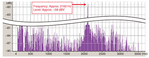
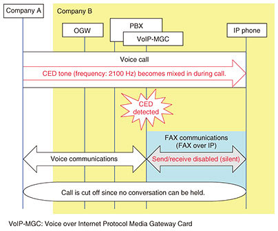
2.2.3 Inference of cause and countermeasureAfter analyzing the collected data, we inferred that one of the causes of this problem was the mixing in of the FAX CED tone from Company A during the call. Consequently, on checking the surroundings near the telephone set at Company A, we found that the telephone set having extension number 25 was installed about 1 m away from the FAX machine, and the machine was transmitting the sound of FAX communications from the speaker used for monitoring its operation. Thus, the monitor sound during FAX communications was picked up by the microphone of telephone number 25. To avoid unintended pickup of the sound, the volume of the monitor sound during FAX communications was decreased. 2.2.4 PBX operation checkIn addition, we also checked the operation of the PBX at Company B. We added a 2100-Hz signal to the voice communication between Company A and Company B. As a result, the voice communication was disabled. Furthermore, on checking the specifications of the PBX equipment, we found that this problem would occur under the following conditions, as shown in Fig. 8.
We confirmed that the equipment configuration at Company B was the same as that at Company A. This means that there was a possibility that the same problem could occur when Company B was making a call with another destination. Therefore, we proposed that the PBX (VoIP Media Gateway Card) should be set to disable the switching to FAX communications mode during a call (set FAX over IP to disabled). This proposal was accepted and implemented, and then problem was solved. 3. ConclusionThis article introduced two case studies of problems occurring in telephone systems in customer premises. The first one described a problem in a key telephone system caused by the timing of transmission of a dial tone in POTS. The other involved a problem in which a PBX would have a misoperation due to picking up a sound in the surrounding area. As we explained here, we use not only modern IP technologies but also conventional PSTN technologies to solve problems in the field. The Technical Assistance and Support Center will continue to provide solutions to problems in the field by using various tools and methods in order to ensure safe and secure telecommunication services. |