|
|||
|
|
|||
|
Practical Field Information about Telecommunication Technologies Vol. 17, No. 12, pp. 40–43, Dec. 2019. https://doi.org/10.53829/ntr201912pf1 Efforts in Preventing Gas Leakage Caused by Movement of Conduit-enclosed Metallic Cables in Bridge SectionsAbstractIn this article, we introduce our efforts to prevent gas leakage caused by cable movement in conduits attached to bridges, for which no effective measures have conventionally been available. This is the fifty-fifth article in a series on telecommunication technologies. Keywords: metallic cable, underground conduit, closure  1. IntroductionThe NTT EAST Technical Assistance and Support Center is continuously working to resolve various failures of communication equipment. There have been no effective countermeasures against leakage of gas* from closures at cable connection points, which occurs when metallic cables laid in conduits in bridge sections move due to vibrations, etc. In this report, our efforts to prevent such cable movement are introduced.
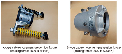
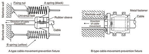
2. Countermeasures for cable movement in underground conduitsFor communication cables laid in underground conduits, a phenomenon called creeping, where the entire cable moves in conjunction with its surroundings, may occur. The following three factors are said to be related to this phenomenon: (i) vibration caused by vehicle traffic (easily generated under a road surface frequently used by large vehicles); (ii) inclination of underground conduits (which are prone to move downward); (iii) ground hardness (i.e., cable movement is likely to occur in soft ground). The cable movement puts a load on the cable inlet of the closure and causes gas leakage. Accordingly, two types of fixtures (A and B in Photo 1 and Fig. 1) are attached to the cable to prevent cable movement based on the standard implementation method. These fixtures prevent movement of the cable in one direction by supporting it via the concrete wall of the manhole duct. These fixtures must be supported by a strong and stable structure (such as a concrete wall) near the underground conduit.
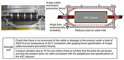
3. Issues concerning bridge sectionsThe metallic cable of a bridge section is laid in a conduit attached to the bridge (e.g., bridge floor). For long-span bridges, closures used as connection points of cables are installed at intervals of a few meters in the conduit. Even in such a bridge section, the cable moves due to vibrations caused by vehicle traffic, etc., and that movement causes gas to leak from the closure. However, strong and stable structures, such as underground manholes, do not exist in these bridge sections, and the conduit itself is not firmly fixed to the bridge; consequently, fixtures for preventing cable movement have not been used effectively. 4. Devising countermeasure product and trialsIn light of the above-described circumstances, the Technical Assistance and Support Center has devised a countermeasure product that can be used even in places where there are no rigid structures. This product (Fig. 2) combines an A-type cable-movement-prevention fixture (Photo 1) and commercially available angle bars. By providing cable grips at both ends of the closure, gripping the cable at regular intervals to bypass the closure, and maintaining the intervals while retaining the shape of the countermeasure product, the product is expected to reduce the load caused by cable movement on the cable inlet of the closure. We therefore installed it on an actual bridge-attached cable and subjected it to a trial.
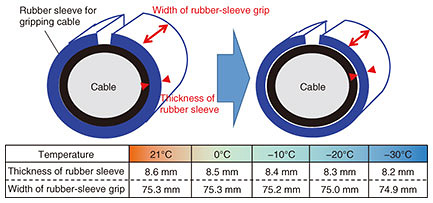
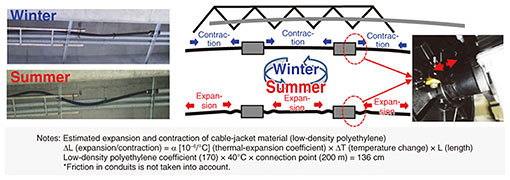
5. Issues concerning countermeasure product and improvementsDuring trials in Hokkaido, where several units of the countermeasure product were installed, it was confirmed that cable movement was not prevented in winter, and after conducting a field survey and verification, the following two facts were revealed. (1) As temperature drops, the rubber of the cable grip contracts, and the expected gripping force cannot be maintained. (2) The entire cable does not move, however, the cable significantly expands and contracts in places due to temperature changes. Regarding fact (1), due to the shrinkage of the gripping material as the temperature decreases (Fig. 3), the gripping force decreases, the cable cannot be gripped, and the cable near the cable inlet repeatedly moves. Regarding fact (2), even at the same installation location, cable expansion and contraction are large in summer and winter and are particularly noticeable in exposed parts of the cable (i.e., cable not covered by the conduit) where the closures are installed (Fig. 4).
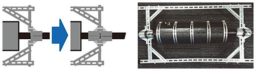
Unlike cable movement in one direction due to vibrations, expansion and contraction caused by this temperature change is repeated in both directions. It is estimated that it is highly likely that gas leaks owing to the increased load on the cable inlet of the closure are caused by the cable entering and exiting the inlet. Therefore, to cope with expansion and contraction due to low temperature or temperature change, two A-type cable-movement-prevention fixtures for gripping were combined (Fig. 5), and a trial is being continued to evaluate the following improvement, namely, increasing the gripping area to ensure that a constant gripping force is maintained even if the gripping material contracts.
6. Future effortsFive units of the improved countermeasure product fixture were installed in 2018 (in two locations and more installed in 2019), and we will continue to check their functionality, durability, and safety while monitoring changes in temperature throughout the years. We also aim to reduce weight and improve workability of the improved countermeasure product by unifying several components into a single unit and thereby reducing the number of bolted parts to ensure its popularization while planning to create an installation manual to instruct maintenance personnel on how to install this product. 7. Concluding remarksIn this article, we introduced our efforts to prevent gas leakage caused by cable movement in bridge sections, for which no effective measures have conventionally been available. This countermeasure is aimed at reducing maintenance operations that have always been difficult to handle and avoiding having to renew cables in the said sections. This will contribute to reducing metallic cable investment and maintenance costs. The Technical Assistance and Support Center will continue promoting efforts to improve the reliability of communication facilities and reduce failures on the basis of our accumulated knowledge and experience as well as application of new technologies. |
|||