|
|||
|
|
|||
|
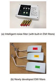
Practical Field Information about Telecommunication Technologies Vol. 18, No. 10, pp. 55–60, Oct. 2020. https://doi.org/10.53829/ntr202010pf1 Quick and Automatic Solution of Electromagnetic Disturbance by Using the Intelligent Noise FilterAbstractThis article introduces the intelligent noise filter developed by Technical Assistance and Support Center, NTT EAST. The intelligent noise filter can quickly and easily suppress an electromagnetic disturbance that may cause problems in telecommunication networks. This is the sixtieth article in a series on telecommunication technologies. Keywords: noise filter, electromagnetic disturbance, frequency detection  1. IntroductionAn electromagnetic disturbance generated from malfunctioning electric/electronic equipment may affect the telecommunication signals being transmitted on a copper cable. An electromagnetic disturbance may cause problems in telecommunication networks such as audible noise in analog telephones, connection loss or quality degradation of Asymmetric Digital Subscriber Lines (ADSLs), and transmission errors on Integrated Services Digital Network (ISDN) lines. To solve these problems, it is necessary to identify the source of the electromagnetic disturbance and remove it. However, this is difficult to do in many cases in the field. An electromagnetic interference suppression (EMI) filter is useful for removing such disturbance when the source of the disturbance cannot be identified. However, to use an EMI filter, service personnel need to use special techniques, such as measuring the frequency of the disturbance and selecting the appropriate EMI filter. Moreover, if an electromagnetic disturbance randomly appears in the cable, it takes time to determine the characteristics of the disturbance. Therefore, Technical Assistance and Support Center (TASC), NTT EAST, developed a new measurement tool for removing electromagnetic disturbance last year. The tool, called intelligent noise filter, can be used to automatically measure the frequency of the electromagnetic disturbance and automatically insert the appropriate EMI filter built into the device into the copper cable [1]. This article introduces key features of and how to use the intelligent noise filter. 2. Key features of the intelligent noise filterThere are many types of EMI filters according to the frequency range and telecommunication services. Therefore, the intelligent noise filter is used to measure the frequency range of the electromagnetic disturbance, making it possible to select the most appropriate EMI filter. A photograph of the intelligent noise filter is shown in Fig. 1(a). It is 45 mm in height, 175 mm in width, and 125 mm in depth and weighs about 500 g. Since it can operate for about 200 hours on four AA alkaline batteries, its power supply at the installation site is not a matter of concern. We also developed three types of EMI filters for permanent measures, as shown in Fig. 1(b). Each filter has the same attenuation characteristic in accordance with the frequency range specified by the main unit of the intelligent noise filter. When the frequency range of the electromagnetic disturbance is determined using the intelligent noise filter, we can replace the built-in EMI filter with the appropriate newly developed EMI filter.
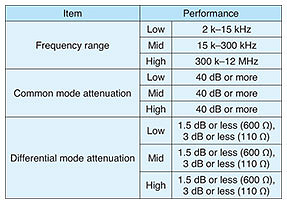
2.1 Noise measurement and filter specificationsThe specifications of the intelligent noise filter and the newly developed EMI filters are listed in Table 1. The intelligent noise filter detects and suppresses noise. To detect noise, the intelligent noise filter measures the frequency range of an electromagnetic disturbance between 2 kHz to 12 MHz. This frequency range is also divided into three bands: 2 to 15 kHz (Low), 15 to 300 kHz (Mid), and 0.3 to 12 MHz (High). To suppress noise, the built-in EMI filters attenuate noise in accordance with three frequency bands.
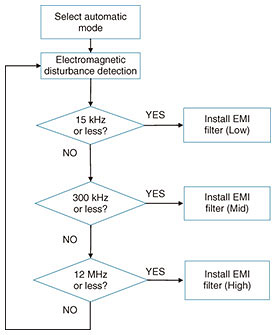
The newly developed EMI filters have the same specifications as the built-in EMI filters in terms of frequency range and attenuation level. Common mode attenuation, which indicates how much electromagnetic disturbance can be suppressed, is 40 dB or more in any frequency range. Differential mode attenuation, which indicates the attenuation of the telecommunication signal, is 1.5 dB or less when they are installed in an analog line and 3 dB or less when installed in a digital line. Both the built-in EMI filters and the newly developed EMI filters effectively suppress electromagnetic disturbance while minimizing its impact on communication quality. 2.2 Noise detectionThe intelligent noise filter automatically detects the frequency range of an electromagnetic disturbance and turns on an indicator corresponding to the detected frequency range (Low, Mid, or High). Electromagnetic disturbance voltage of –20 dBV (0.1 V) or higher can be detected, and it is possible to adjust the detection voltage level from –10 dBV (0.3 V) to –40 dBV (0.01 V) by adjusting the detection sensitivity volume. 2.3 EMI-filter-installation modeThe intelligent noise filter has two modes, i.e., manual and automatic, to install one of the built-in EMI filters according to the detected frequency range. Manual modeThe appropriate built-in EMI filter can be applied by pressing the button corresponding to the detected disturbance-frequency range indicated by the illuminated indicator. Automatic modeWhen an electromagnetic disturbance is detected, the built-in EMI filter corresponding to that frequency range is automatically applied. The application flow of the corresponding filter when automatic mode is set is shown in Fig. 2.
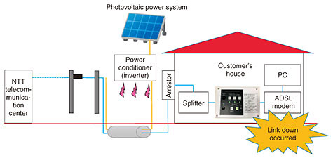
2.4 Using the intelligent noise filterThe intelligent noise filter is used according to the following procedure. (1) Install the intelligent noise filter on a copper cable, on which audible noise, transmission error, or other problems caused by electromagnetic disturbance have occurred, and switch its power supply on. (2) When an electromagnetic disturbance occurs, the intelligent noise filter automatically detects it, and the indicator corresponding to the detected frequency range is illuminated. In manual mode, a service personnel presses the button corresponding to the detected frequency range to apply the appropriate built-in EMI filter (Low, Mid, or High). In automatic mode, the intelligent noise filter automatically applies the built-in EMI filter that corresponds to the frequency range of the detected noise. (3) After confirming the effect of the built-in EMI filter, that filter is replaced with the corresponding newly developed EMI filter (Low, Mid, or High) for permanent measures. 3. Countermeasures using the intelligent noise filterPractical countermeasures using the intelligent noise filter are described in this section. 3.1 Countermeasure against telecommunication problems occurring on an ADSLA customer who uses an ADSL reported that a link down of the ADSL frequently occurs. Although local service personnel took countermeasures such as replacing the ADSL modem, the link down could not be resolved. Therefore, TASC investigated the electromagnetic disturbance and implemented a countermeasure by using the intelligent noise filter (Fig. 3).
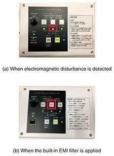
First, when the intelligent noise filter was installed between the ADSL modem and splitter, the Mid indicator was illuminated (Fig. 4(a)). Then, when the button of the Mid filter was pressed, i.e., the built-in EMI filter (Mid) was applied, the link down of the ADSL was resolved (Fig. 4(b)). Finally, TASC replaced the built-in EMI filter (Mid) with the newly developed EMI filter (Mid) for permanent measures.
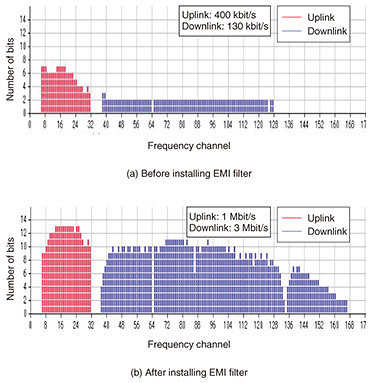
The transmission rate of the ADSL was improved by installing the appropriate newly developed EMI filter. The results of the measured bit maps before and after installing the filter are shown in Fig. 5. Transmission rate increased from 400 kbit/s to 1 Mbit/s on the uplink and from 130 kbit/s to 3 Mbit/s on the downlink.
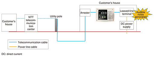
TASC also investigated the source of the electromagnetic disturbance and found that it was being generated by the power conditioner of a photovoltaic power system installed near the customer’s house. The noise was being transmitted through the power line cable and induced in the telecommunication cable, which was laid out parallel to it, thereby affecting the ADSL signal. 3.2 Countermeasure against audible noise occasionally heard on 3.4k leased lineA customer who uses a 3.4k leased line between two locations reported an audible noise (a “bee” sound) mixed into the telephone signal at an occurrence frequency of once a week. Local service personnel had difficulty in responding to the problem because the audible noise was not generated when they visited the customer’s house. Therefore, TASC investigated the noise and implemented a countermeasure using the intelligent noise filter (Fig. 6).
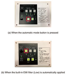
The intelligent noise filter was installed between the leased-line terminal and arrester in the customer’s house. Since the disturbance occurred sporadically, the automatic-mode button was pressed to detect and monitor the disturbance for one week (Fig. 7(a)). After that week, the customer informed us that the audible noise no longer occurred, so when the service personnel visited, the Low indicator was illuminated and the built-in EMI filter (Low) was applied automatically (Fig. 7(b)). Subsequently, that filter was replaced with the newly developed EMI filter (Low). It was found that low-frequency noise entered the power line cable. Thus, the source of the disturbance was determined as the power-supply unit or the power-supply source that starts up irregularly.
4. Concluding remarksThe key features of the intelligent noise filter developed by TASC were introduced and actual countermeasures against telecommunication problems caused by electromagnetic disturbance were described. From these countermeasures, using the intelligent noise filter makes it possible to recover from telecommunication problems caused by electromagnetic disturbance without the need for specialist skills; accordingly, it is expected to alleviate the implementation of countermeasures against such problems. To reduce telecommunication problems caused by electromagnetic disturbance, radio, induction, lightning, etc., and improve the reliability of telecommunication services, the EMC Engineering Group in TASC will continue to actively engage in technical cooperation and development and disseminate their technologies through activities such as technology seminars. Reference
|
|||