|
|||||||||||||||||||||||||||
|
|
|||||||||||||||||||||||||||
|
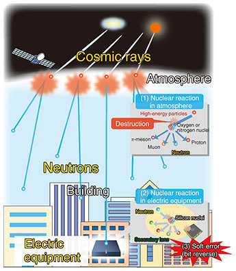
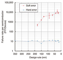
Regular Articles Vol. 19, No. 6, pp. 94–103, June 2021. https://doi.org/10.53829/ntr202106ra1 Neutron-energy-dependent Semiconductor Soft Errors Successfully Measured for the First TimeAbstractProblems caused by neutron-induced soft errors in electrical devices are becoming increasingly common in various applications. The neutron-energy-dependent soft-error rate is indispensable for evaluating the frequency of such errors in different neutron environments. We observed the energy-dependent neutron-induced soft-error rates continuously over the energy range of 1–800 MeV at the Los Alamos Neutron Science Center, USA. This measurement was made possible with a method we developed that uses extremely fast circuits built into field-programmable gate arrays coupled with a neutron time-of-flight technique. Keywords: soft error, cosmic rays, field-programmable gate arrays (FPGAs)  1. IntroductionModern society’s infrastructures are becoming increasingly dependent on digital technologies and are undergoing a digital transformation. Although people enjoy greater convenience in their everyday lives, various issues such as software bugs in electrical device logic and security compromises have become major social problems. There are also random phenomena called bit errors in semiconductor devices such as in large-scale integrated circuits (LSIs) including memory chips. Soft errors caused by cosmic rays are a type of bit errors [1], but there are many cases in which the causes are unknown, making them very difficult problems to solve. Neutrons generated by cosmic rays are currently the main cause of soft errors in semiconductor devices of electrical equipment used on the ground [2, 3]. When cosmic rays arrive from outer space, they collide with oxygen or nitrogen nuclei in the atmosphere, generating various secondary particles by a spallation reaction (Fig. 1). Neutrons have particularly high penetrating power because they are uncharged and can pass through the concrete structures of buildings. When neutrons pass through a semiconductor device on an electrical circuit board, they can interact with a silicon nucleus and generate secondary ionizing particles, though this is very rare. The ionizing particles can reverse internal logic states in the chip, referred to as a single event upset (SEU). The rate of SEUs per device (unit area) becomes non-negligible as the degree of LSI integration becomes greater. This is because the design rule, which is related to the minimum processing line width, becomes narrower each year, and the critical charge to cause an SEU lessens along with the line width. Recent progress in larger integration and increasingly finer microfabrication technologies has resulted in a dramatic increase in the occurrence of soft errors in contrast to hard errors that permanently disable semiconductor devices [4]. Figure 2 shows the relationship between the design rule and failure in time (FIT), which is the number of failures per billion hours per device, in static random access memory (SRAM)-based field programmable gate arrays (FPGAs). The rate of multiple bit upsets is increasing with narrowing design rules. For example, in a real-world information network consisting of 10,000 communication units, each with 5 of the 10,000 FIT LSIs in stacks, about 12 soft errors will occur on a daily basis. At this rate, network operators would not be able to handle all errors. Also, soft errors may cause network equipment to be hung up, leading to breakdown in some network services. In a worst case scenario, the breakdown can occasionally become widespread. Therefore, SEUs are not limited to occurring in information network devices but also in various other electrical devices. Consequently, SEUs may have a serious impact when such devices are incorporated into medical instruments, automobiles, airplanes, trains, and personal computers (PCs), to name but a few.
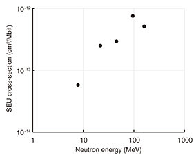
Therefore, it is crucial to design and fabricate semiconductor devices and systems to minimize the SEU error rate measured in FIT units to ensure the reliability and safety of these devices and systems. To calculate the expected number of failures due to soft errors in various neutron environments (natural, space, building, accelerator, nuclear plant, underground, etc.), the number of neutrons per unit time at each neutron energy, and the SEU cross-section at this energy are required for a wide energy range of impinging neutrons. The SEU cross-section depending on the neutron energy σSEU(En) is defined as which identifies a neutron fluence Φ(En) as the total number of neutrons per unit area impinging on the semiconductor device and the total number of SEUs, NSEU(En), generated by these neutrons. Specifically, σSEU(En) indicates the probability that one neutron per unit area causes a soft error. Note that the SEU cross-section for each neutron energy will differ for each semiconductor device. In addition, neutrons in the natural environment and those generated by accelerators have distinct energy distributions. Therefore, the soft error rate (SER) in a specific neutron-irradiation environment can be defined as using the neutron flux φ(En) (number of neutrons with En crossing a unit area in a unit time) at each neutron energy and σSEU(En). Thus, the SEU cross-section is the most important basic datum necessary for calculating the failure rate of semiconductor devices due to soft errors. However, the SEU cross-section has been measured at only a few points in the neutron energy range from 1 to 176 MeV [5, 6] (Fig. 3). As a consequence, there are no data on SEU cross-sections continuously covering a wide range of neutron energy using this method, so the whole picture of the cross-section is yet to be clarified.
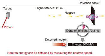
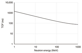
Therefore, we attempted to measure energy-resolved SEU cross-sections by using the neutron time-of-flight (TOF) technique for a wide neutron energy range. Accordingly, we developed a method of detecting errors in the desired time resolution using FPGAs and measured SEU cross-sections using the TOF technique at the Los Alamos Neutron Science Center (LANSCE), USA. 2. Measurement methods2.1 TOF techniqueThe TOF technique makes it possible to determine the neutron velocity ν (i.e., En) by measuring the flight time of a neutron along a flight path with a known length. In the sub-GeV region, neutrons have velocities close to the speed of light; thus, we need to consider the relativistic effects. The En is determined as 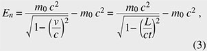 where m0 is the neutron rest mass, v is its velocity, c is the velocity of light, L is the flight path length, and t is the neutron flight time. Using the TOF technique, it is possible to determine the energy of the neutron that caused a soft error by measuring the time at which the soft error occurred. The TOF of the sub-GeV is very short, for example 1.4 µs at 1 MeV and 79.3 ns at 800 MeV with the LANSCE L = 20 m (Fig. 4). Therefore, we chose a duration of 8 ns for detecting SEUs to obtain a time resolution of Δt/t = 10% at 800 MeV (Fig. 5). However, it is impossible to measure TOF in the desired time resolution using conventional SRAM. Furthermore, because an ordinary SRAM reads data sequentially, it takes several milliseconds to scan sufficient data for soft-error detection. This makes it impossible to conduct nanosecond-order TOF measurements by using SRAM. Even if many sets of SRAM and memory-readout circuits are fabricated using on-chip SRAM in an FPGA, it is impossible to scan several M bits in nanoseconds. Therefore, we designed circuits that can detect a soft error due to a malfunction in logic circuits composed of configuration random access memory (CRAM) that determines the logic of the FPGA. In this case, determination of a CRAM bit error is possible at the operating frequency of the FPGA. It is also possible to monitor a capacity equivalent to several 10-M-bit FPGAs. We devised a circuit that can detect an SEU in nanoseconds and conducted SEU cross-section measurements of FPGAs depending on the neutron energy using the TOF technique.
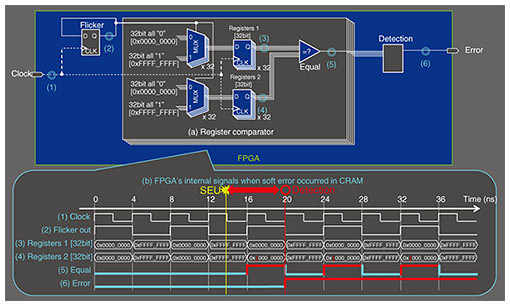
2.2 Soft-error detection in nanoseconds using FPGAsWe first considered using the cyclic redundancy check (CRC) circuit, which can detect the CRAM errors, built into modern FPGAs to obtain TOF information. An FPGA stores circuit design data in an SRAM-based CRAM and program logic circuits and wiring using bits of the CRAM. When a CRAM bit is inverted by an SEU, it is immediately transmitted to a logic circuit or a wiring, which is not the effect intended by the programmer of the FPGA. Recent FPGAs can detect bit errors by CRC to detect soft errors of the CRAM. However, the neutron energy cannot be specified with the TOF technique from the CRC of a CRAM because a detection time of several tens of milliseconds is required to check all the CRAM bits. Therefore, we focused on any logic malfunction in the circuit caused by CRAM errors. When a bit error occurs in a CRAM bit related to circuit operation, the circuit operation changes immediately, and a logic malfunction occurs. Since FPGA circuits can operate at several hundred megahertz, a logic malfunction can be detected in nanoseconds by programming user circuits to detect the malfunction. For this purpose, we programmed a user circuit that has a large number of registers and monitors. The basic principle of this measurement is shown in Fig. 6. This FPGA, which is also a device under test (DUT), operates at 250 MHz and outputs an error signal that triggers the TOF signal when a logic error occurs due to a soft error. As shown in Fig. 6, register comparator units (Fig. 6(a)) consist of two multiplexer units (MUXs), two 32-bit registers, and a comparator detecting a logic malfunction. Logic malfunction is detected by comparing the two output signals of the MUXs. Figure 6(b) shows a timing diagram of the FPGA’s internal logic at signal monitoring points (1) to (6) when a soft error occurred in the CRAM. The output of the registers repeats all “0” (0x0000_0000) or all “1” (0xFFFF_FFFF) alternately in accordance with the flicker select signal. If none of the comparison results match, the detection module asserts an error and outputs it as a TOF trigger signal. The operation of each MUX is controlled by the look-up table (LUT) in the FPGA. The registers are all 32-bit ones, but we first focus on only one bit of them. The flicker signal is fed into one of the 4-bit input lines in the LUT, and all the other three lines are set to “0”. As a result, one of the two SRAM bits is selected; one is initially set to 1 and the other 0, resulting in the time series of alternative “1” and “0”. A corresponding bit pattern of the desired logic is stored in a 16-bit (= 24-bit) CRAM. When a condition is put into the 4-bit input lines, the result is output to the 1-bit line. The result is then held by a flip-flop circuit.
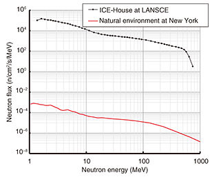
When a CRAM bit is inverted, therefore, an incorrect value is written to the register at the next clock timing. There are two identical 32-bit registers, but only one register output is affected by the soft error; therefore, by comparing the two registers, the error is detected with this circuit. When this circuit is operated with a 250-MHz clock, logic malfunction can be detected within 8 ns. The neutron energy can then be specified by obtaining the difference between the time at which neutrons were generated and the timing ((6) in Fig. 6) at which a logic malfunction was detected in a few-nanosecond resolution. 2.3 FacilitiesThere are four requirements for an accelerator facility to execute this measurement. The first is a pulsed neutron source with a short pulse width. To measure high-energy neutrons using the TOF technique, the duration of the pulse of the accelerated particles entering the target is preferably 1 ns or less with a flight path of about 20 m. Note that this requires a beamline through which you can directly view the neutron production target without a neutron moderator from the position of DUTs. The second requirement is a high-energy white neutron source. To measure a wide En range up to hundreds of mega electronvolts, the neutron source driven by a high energy proton accelerator is indispensable. The third requirement is that the incident neutron energy spectrum should be available or measurable within a specified precision. It is crucial to calculate an SEU cross-section. The final requirement is that neutron intensity should be high enough. In this experiment, it took time to obtain data with satisfactory statistical accuracy because the logic malfunction rate with our method is lower than that of CRAM as a whole. In addition, to obtain a precise energy-dependent cross-section by using the TOF technique, a very high intensity neutron source is required to obtain high statistical accuracy in a short time bin for high energy resolution. The best accelerator facility that satisfies the above requirements is the ICE-House or ICE-II at LANSCE [7, 8]. LANSCE is based on an 800-MeV proton linac with relatively long pulse width but has a storage ring to compress the beam. It uses a short proton beam pulse of 125 ps. Figure 7 shows the neutron energy spectrum measured in a fission chamber installed 19.7 m from the target at LANSCE, together with the neutron spectrum in a natural environment [9]. Thus, LANSCE has a neutron energy spectrum close to that in the natural environment, with about four orders of magnitude higher neutron flux.
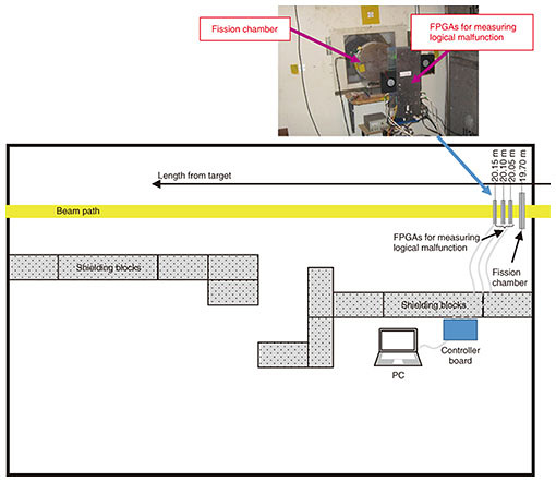
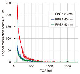
3. ExperimentWe conducted the experiment at the ICE-House in LANSCE involving irradiating DUTs, which were three types of commercially available FPGAs with design rules of 28, 40, and 55 nm. We measured logic malfunctions as a function of neutron energy. The experimental setup at the ICE-House is shown in Fig. 8. The experimental area is separated into two sections by thick concrete and polyethylene walls. One of the sections contains the neutron beam (beam area), in which the DUTs are placed. The yellow line shows the neutron beam entering from the right and exiting to the left. The other section is equipped with all the monitoring equipment (controller board and PC). The fission chamber was installed at a distance of 19.70 m from a tungsten neutron production target. The FPGAs were installed at distances of 20.05, 20.10, 20.15 m.
The controller board calculates the time difference between the proton pulse and error signal and executes recovery control of the FPGAs. The controller board outputs the time difference to the PC. 4. Results and discussionThe TOF spectra of the number of logical malfunctions of the three FPGAs are shown in Fig. 9. The total number of logical malfunctions in each FPGA was as follows: 28-mm FPGA, 12,713; 40-mm FPGA, 2894; and 55-mm FPGA, 3719.
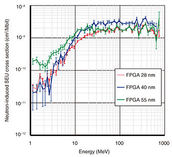
Figure 10 shows the CRAM SEU cross-sections calculated from the measured logical malfunction time distribution, number of CRAM errors, and neutron fluence [10, 11, 12]. The SEU cross-sections tended to increase rapidly from 3 to 20 MeV and remain almost constant thereafter. There was a difference in the absolute value of the cross-sections among the three FPGAs, although they were similar. In the energy range from 1 to 3 MeV, the difference in the cross-sections was significant. The device type for the simulation conducted by Abe and Watanabe [13] was not the same as the devices used in this experiment, but the trend of the measured SEU cross-sections was similar to that in their simulation. From their simulation, they found that SEUs below 5 MeV are attributed to elastic recoils of oxygen and silicon ions. They also found that the sharp increase in an SEU cross-section appears near the threshold energies of the (n, p) and (n, α) reactions caused by secondary helium and hydrogen ions. Their simulation showed that the sharp increase in gradient is enhanced by making the critical charge smaller. Generally, the smaller the design rule, the smaller the critical charge tends to be, but the 40-nm FPGA showed the largest sharp increase. We infer the reason for this is that the 28-nm FPGA uses high-k metal gate (HKMG) technology. An HKMG achieves a high dielectric constant by having metal for the gate. As a result, both the gate capacitance and critical charge increases, so it is speculated that the 28-nm FPGA had a milder increase than the 40-nm one. To confirm this, it is necessary to conduct measurements with an HKMG and silicon dioxide gate devices under the same design rules.
5. ConclusionWe measured the SEU cross-sections with high energy resolution from 1 to 800 MeV at the ICE-House of LANSCE with our method of measuring the neutron-induced SEU cross-sections for FPGAs using the TOF technique. The results clarified the complete picture of the SEU cross-sections. The most important contribution of these cross-sections is that they enable us to calculate the SERs in any type of neutron environment. References
|
|||||||||||||||||||||||||||