 |
|
|
|
|
|
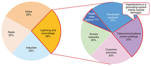
Practical Field Information about Telecommunication Technologies Vol. 19, No. 8, pp. 58–63, Aug. 2021. https://doi.org/10.53829/ntr202108pf1 Grounding-system Evaluator for Preventing Lightening Damage to Telecommunications Center BuildingsAbstractThis article provides information on lightning damage to telecommunications center buildings and introduces the grounding-system evaluator developed by Technical Assistance and Support Center. The evaluator supports the investigation of the status of grounding systems, which includes telecommunication, power, and grounding installations. The evaluator also suggests methodologies for improving grounding systems in preventing telecommunication and power equipment from being damaged by lightning. This is the sixty-fifth article in a series on telecommunication technologies. Keywords: lightning damage, grounding system, grounding-system evaluator 1. IntroductionWhen lightning strikes a telecommunications center building or nearby, it can cause damage or malfunction of telecommunication and power equipment. The damage may have a significant impact on the equipment in such buildings, and it can take a long time to restore telecommunication services. Therefore, it is important to prevent telecommunication and power equipment from being damaged by lightning. Figure 1 shows the percentage of technical consultations classified by causes and damaged objects from the EMC Engineering group of Technical Assistance and Support Center (TASC) in fiscal 2019. Lightning-related technical consultations accounted for 26% of all consultations, and 30% of those consultations were related to lightning damage to telecommunications center buildings and radio relay stations. By analyzing the lightning damage in telecommunications center buildings, it was found that the damage was mainly caused by imperfections in the grounding systems, such as lack of wire connection and isolation.
The most important countermeasure against lightning damage to telecommunications center buildings is improving the grounding systems. However, to improve grounding systems, service personnel need to have correct knowledge on the grounding, investigation procedure, and how to solve the problems which are found in the investigation, such as lack of wire connection and isolation. To solve these problems, TASC prepared a document for providing “investigation and improvement methodologies and procedures for grounding systems in telecommunications center buildings.” TASC also developed a grounding-system evaluator that supports the investigation of and improvement in such systems. This article introduces this evaluator and a field case study. 2. Grounding-system evaluatorThe grounding-system evaluator can visualize a configuration of the grounding system that includes the connection between the telecommunication and power equipment and cable. It also points out imperfections in the grounding configuration in accordance with the above document. Figure 2 illustrates the use of the grounding-system evaluator.
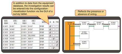
2.1 Configuration-visualization functionThe configuration-visualization function is illustrated in Figure 3. The existing data of wiring connection, which are formatted by excel or csv, can be imported from the equipment database. This function enables users to reduce the time to input the grounding-system configuration and makes it possible to easily visualize the status/condition of telecommunication facilities, such as equipment, cables, and grounding cable, in telecommunications center buildings. It is also possible to visualize the results obtained through on-site investigations via a graphical user interface (GUI) and reflect them in the above visualization.
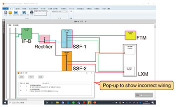
2.2 Function for automatically determining the status of a grounding configurationThe function for automatically determining the status of a grounding configuration is illustrated in Fig. 4. This function visualizes whether the status of the grounding configuration is correct. The evaluator investigates the 30 items for ideal grounding system described in the document of investigation and improvement procedures and methods written by TASC. If a fault is found, the evaluator shows the details of this fault. This means that users can easily find the areas to be improved. Thus, this function is not only useful for maintaining grounding systems but also makes design work more efficient.
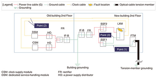
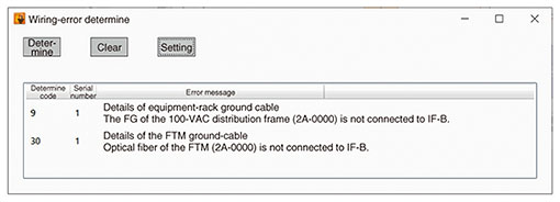
3. Case study of countermeasures TASC proposed against lightning-damage failure using the grounding-system evaluatorA case study of a countermeasures proposed by TASC using the grounding-system evaluator against lightning damage in a telecommunications center building is presented in this section. 3.1 Failure statusDue to lightning, the Subscriber Lines Cross-Connect Module (LXM) system failed and many customer services stopped for a considerable time. Although the system was recovered by restarting the LXM packages, TASC was asked to investigate the cause of the failure and propose countermeasures to prevent the lightning damage.3.2 On-site investigation and simulation using the grounding-system evaluatorThe status of a grounding-system configuration obtained from the on-site investigation is shown in Fig. 5, and points to be addressed are listed in Table 1. Figure 6 shows the simulation results of the grounding-system evaluator, focusing on the fiber termination module (FTM) on the second floor of the new building and Figure 7 shows details of wiring errors. The simulation results show that the wiring between the FTM and SSF1 (a power supply distributor) is incorrect, and the FTM should be wired to Interface – B (IF-B).
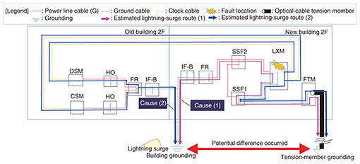
3.3 Estimation of causesOn the basis of the results obtained from the investigation, the estimated invading route of the lightning surge that caused the failure is shown in Fig. 8 and Table 2. Due to the increase in the ground potential caused by the lightning strike near the telecommunications center building, a potential difference occurred between the building ground and tension-member ground. Thus, a lightning surge current was generated and propagated through cables, i.e., the lightning-surge current flowed from the ground cable into the LXM via the metal cables and flowed out to the ground cable and clock cable.
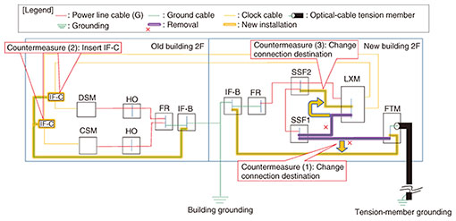
3.4 Lightening countermeasuresThe countermeasures that were proposed against the above lightning damage in this case study are shown schematically in Fig. 9 and described as follows.
Countermeasure (1): To pass the lightning surge directly to the optical-cable tension member of the FTM, the ground cable between SSF-1 and the FTM should be removed, and the FTM should directly connect to IF-B in the new building. Countermeasure (2): To pass the lightning surge flowing into the LXM from the clock cable, two IF-Cs are inserted into the clock cables crossing the buildings from the DSM and CSM, and the ground terminal of the IF-Cs should connect to IF-B in the old building. Countermeasure (3): To make the SSF-2 and LXM equipotential, SSF-2 should connect to the LXM instead of SSF-1 and LXM. 4. ConclusionThis article described the grounding-system evaluator developed by TASC. By conducting a field-survey of lightning damage that occurred at a telecommunications center building, TASC could find the causes of the failure and proposed countermeasures to prevent lightning surge. The evaluator can visualize the configuration of a grounding system, which includes telecommunication equipment, power equipment, and grounding cables. It can also automatically determine the status of the configuration. The EMC Engineering group in TASC is continuously engaged in technical support in the field regarding problems caused by lightning, malfunction of electromagnetic phenomena, interference of radio wave, induction from power line, and so on to ensure reliability of telecommunication services. |

