|
|||||||||||||||
|
|
|||||||||||||||
|
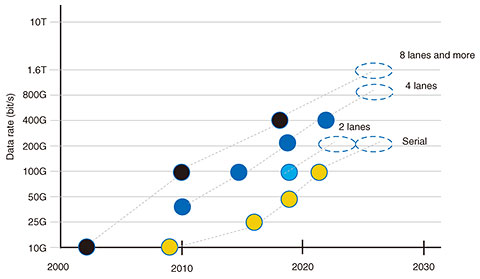
Global Standardization Activities Vol. 19, No. 10, pp. 61–66, Oct. 2021. https://doi.org/10.53829/ntr202110gls Latest Trends in 400- and Beyond 400-Gbit/s Ethernet Standardization in IEEE 802.3AbstractThe IEEE (Institute of Electrical and Electronics Engineers) 802.3 Working Group has been proceeding with high-speed point-to-point Ethernet standardization to address increasing communication bandwidth demand in datacenter and telecom networks. Discussion has begun on beyond 400-Gbit/s Ethernet as a next-generation rate of Ethernet. This article explains the trends in the standardization of 400-Gbit/s and beyond 400-Gbit/s Ethernet. Keywords: IEEE 802.3, Ethernet, optical interface  1. Standardization of high-speed Ethernet in IEEE 802.3Ethernet is a standard defined in the IEEE 802 LAN/MAN standardization committee, which develops standards related to local area networks (LANs) and metropolitan area networks (MANs) in the Institute of Electrical and Electronics Engineers (IEEE), and has been used broadly in telecom networks from access to core, as well as datacenter, enterprise, and automobile networks. In the committee, the specifications for the link and physical layers (PHY)*1 have been defined in the 802.3 Working Group (WG) while expanding the application coverage (Fig. 1). The highest standardized interface speed is 400-Gbit/s Ethernet (GbE). The discussions on 400GbE standardization started in May 2014 in the 802.3bs Task Force (TF), and the standardization of the first-generation specification was completed in December 2017. New specifications were then added to increase the area of applications and achieve further cost reductions. Discussions on a higher rate of Ethernet started as the IEEE 802.3 Beyond 400 Gb/s Ethernet Study Group (SG) in January 2021. The SG is responsible for defining the objectives of the beyond 400GbE standardization, such as rates and reaches, before defining the technical specifications in the TF. Therefore, the standardization on beyond 400GbE is in an important initial phase to determine future standardization directions.
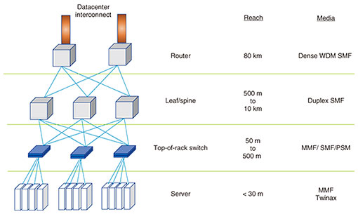
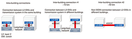
2. Applications of high-speed EthernetDatacenter and telecom networks are important application areas of point-to-point (P2P) high-speed Ethernet. In datacenter applications, transmission specifications are defined in accordance with the floor layout and networking hierarchy. Figure 2 shows typical use cases in a datacenter. The transmission reach between servers and top-of-rack switches is less than 30 m. For such connections, twinax cables or multimode fibers are used as the transmission media. From top-of-rack switches to a higher-level switch, the reach is up to 500 m and multi-mode fibers (MMFs) or parallel single mode fibers (PSMs) are used as the media. For longer reach up to 10 km, single mode fibers (SMFs) are used. There are two typical SMF use cases in telecom network applications. One is usage inside buildings as a client interface of a long-haul transmission system. The other is usage of a non-wavelength division multiplexing (WDM) optical interface for inter-building connections. For intra-building applications, an optical interface of less than a 10-km reach is used. For inter-building applications, a 40-km interface is used as well as a 10-km interface (Fig. 3).
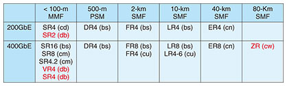
3. History of high-speed Ethernet interfacesThe Ethernet interface has been evolving to higher speed through multiple means, such as parallelization of fibers and lanes, WDM, increase in modulation speed, and adoption of higher-order modulations. In the 10GbE market, a serial interface has been the mainstream implementation, but multi-lane was adopted for 40GbE and 100GbE by using 10-Gbit/s/lane and 25-Gbit/s/lane modulation speeds, respectively. For 400GbE, 4-level pulse amplitude modulation (PAM4) was adopted for the first time. PAM4 can achieve a two times higher data rate using the same modulation speed compared with the conventional non-return-to-zero transmission scheme. 4. 400GbE specification4.1 400GbE defined in 802.3bs TFThe first 400GbE specification was standardized in the 802.3bs TF (May 2014 to December 2013) on the basis of the objectives defined in the 400GbE SG, which started in May 2013. In this TF, 200GbE was standardized as well as 400GbE to satisfy demand from the datacenter market [1]. Table 1 shows the specifications of 200GbE and 400GbE, including works in progress.
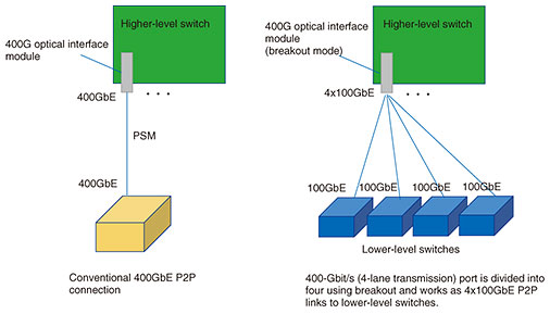
In the 802.3bs TF, 500-m PSM (400GBASE-DR4, 200GBASE-DR4), 2-km SMF (400GBASE-FR8, 200GBASE-FR4), and 10-km SMF (400GBASE-LR8, 200GBASE-LR4) were defined for both 200GbE and 400GbE. In 500-m PSM, breakout connections, such as 4x100 and 4x50 Gbit/s, where the lanes are separated and used independently, are used for connections from top-of-rack switches to a higher-level switch (Fig. 4). This is a connection that uses the speed per lane, which is 100 or 50 Gbit/s, in PSM transmissions. For 400GBASE-DR4 with a 500-m reach, in addition to adoption of PAM4 modulation, higher modulation speed (about 50 GBaud) was adopted for the first time, and 400 Gbit/s was achieved by four lanes of 100 Gbit/s/lane. Regarding the 2- and 10-km optical interface specifications, where the reach is required to be longer than 500 m, the same modulation speed with 100GbE (25 GBaud) is used, and 400GbE is achieved by 8x50 Gbit/s/lane with PAM4. The connections to the area router in datacenter buildings uses 2-km SMF specifications while used for connections between client equipment to long-haul transmission equipment in telecom buildings. Regarding 10-km specifications, 400GBASE-LR8 and 200GBASE-LR4 were originally targeted for inter-building connection usage in telecom networks. However, because of the advantages of a larger loss budget compared with 2-km specifications, these interfaces are also being used by datacenter operators for high loss link.
4.2 400GbE specification improvementAfter the 802.3bs TF is completed, there were two activities to expand and improve 200GbE and 400GbE specifications, i.e., beyond 10 km and 100 Gbit/s/lambda. The Beyond 10 km SG was an activity to define interface specifications that can cover more than 10-km transmission for 25GbE, 50GbE, 200GbE, as well as 400GbE. This standardization activity was initiated to cover inter-building connection usage in telecom mobile backhaul networks. However, the scope was expanded to include cable systems and datacenter applications at the SG phase. At the TF formation phase, 400GbE standardization work in the Beyond 10 km SG were split into two TFs, 802.3cn and 802.3cw. In 802.3cn, 400GBASE-ER8, which is a specification that supports up to 40-km reach over SMF, was standardized. The implementation of a 40-km reach interface can be achieved by improving the performance of the existing 50-Gbit/s/lane transmission scheme used in 400GBASE-LR8 by additionally applying a high-sensitivity component called an avalanche photo diode at the receiver side [2]. The 802.3cw TF is still in progress and is defining a specification to achieve 80-km transmission over a P2P dense WDM (DWDM) system with 75-GHz channel spacing. This TF is reusing the Optical Internetworking Forum (OIF)*2 400G-ZR specification [3], which is an interface specification for 100-GHz-spaced DWDM defined prior to IEEE 802.3cw in OIF. IEEE 802.3 is introducing support for a 75-GHz grid on the basis of IEEE 802.3 standardization criteria. The second activity to expand 400GbE specification, 100 Gbit/s/lambda, is targeting cost and power-consumption reduction by reducing the number of lanes in the optical interface by using 100 Gbit/s/lane instead of 50 Gbit/s/lane. This standardization activity progressed as 802.3cu by a strong request from datacenter operators who plan a large-volume deployment in hyper-scale datacenters. Regarding the 400GbE specification in 802.3cu, 400GBASE-FR4 was defined for 2-km reach using 100-Git/s PAM4, and 400GBASE-LR4-6 was defined to cover 6-km reach. The activity originally targeted 10-km-reach standardization. However, considering the worst-case condition based on IEEE 802.3 criteria for interoperability and backward compatibility, the reach limit was considered as 6 km. As a result, 400GBASE-LR4-6 standardization was completed as a 6-km reach specification over SMF.
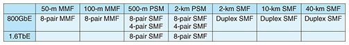
5. Beyond 400GbE standardizationThe Beyond 400GbE SG started in January 2020. Discussions on target rate and reach are currently underway in this SG. Currently, 800 Gbit/s and 1.6 Tbit/s have been adopted by motion as new Ethernet Media Access Control (MAC)*3 rates. There are also many reach targets for Ethernet PHY mainly targeting datacenter applications. 5.1 Current status of beyond 400GbE discussionTo move standardization to the next-generation Ethernet rate, the Beyond 400G SG [4] was started on the basis of the consensus built by the IEEE 802.3 ad-hoc group. From the investigation of the ad-hoc group, a higher rate of Ethernet will be required around 2025 to address continuously increasing communication traffic including new needs of data communication such as fifth-generation mobile communications, artificial intelligence, and virtual reality as well as existing applications. Applications and the necessary reaches of interfaces will be mostly the same as 400GbE standards. However, one difference is that the use case of breakout connection is clearer and becoming more important compared with the time of 400GbE standardization. Therefore, the maximum speed achievable per lane and number of lanes are important in determining the standardization directions. On the basis of the assumptions that maximum lane speed achievable in the project timeframe is 200 Gbit/s/lane, 800-Gbit/s MAC has been adopted as project objectives because it enables 4x200- and 8x100-Gbit/s breakout connections. In addition to 800-Gbit/s MAC, 1.6-Tbit/s MAC has been included into the objectives to flexibly and promptly address potential user requirements for higher speed, as it can support 8x200 Gbit/s. Table 2 shows the currently adopted objectives in the Beyond 400G SG. Because the usage of breakout connections is explicitly assumed, there are multiple interface specifications with the same distance but different number of lanes.
5.2 Beyond 400GbE discussion perspectiveOptical interfaces discussed in the Beyond 400G SG are planned to be used with next-generation 51.2- and 104.8-Tbit/s capacity Ethernet switches based on datacenter user requirements. In these next-generation switch implementations, the switch application-specific integration circuit (ASIC) and Ethernet PHY can be integrated to reduce power consumption in the electrical path inside a switch. Conventional Ethernet had an explicit interface definition between the switch ASIC and Ethernet PHY to achieve a pluggable transceiver module. Therefore, it would be a new discussion point to consider integrated implementation of the switch ASIC and Ethernet PHY in the standardization. Another discussion point is transmission technologies used for beyond 400GbE optical interfaces. The current SG is responsible for investigating the market demands and technical feasibility to define the objective of the standardization; therefore, a detailed transmission scheme will be discussed in the following TF phase. However, technical hurdles will be higher to achieve reach as the modulation rate becomes higher. Therefore, PAM4 transmission is thought not to be enough to achieve all the objectives. The SG may have to consider coherent transmission to show that the technical feasibility and coherent transmission usage will be increased in the next-generation Ethernet specifications.
References
|
|||||||||||||||