|
|||||
|
|
|||||
|
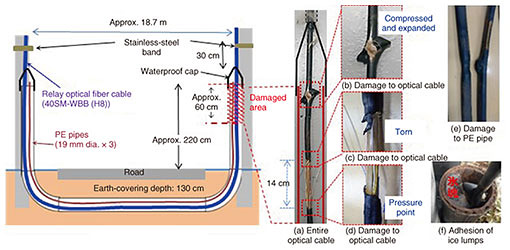
Practical Field Information about Telecommunication Technologies Vol. 19, No. 10, pp. 67–71, Oct. 2021. https://doi.org/10.53829/ntr202110pf1 Investigation on Damage to Optical Fiber Cables Caused by Freezing and Thawing of Water in a Lifting PipeAbstractThis article introduces an investigation into the mechanism of damage to optical fiber cables and polyethylene pipes in lifting pipes installed in cold regions. We carried out examinations using a physical simulation model in a large thermostatic room. This is the sixty-sixth article in a series on telecommunication technologies. Keywords: optical fiber cable, lifting pipe, freezing and thawing  1. IntroductionA lifting pipe attached to a utility pole is used where an underground optical fiber cable goes up to ground level. In cold regions, an optical fiber cable in the pipe sometimes becomes damaged due to the accumulated water freezing in the lifting pipe. To prevent such damage, two measures are taken: (i) installing waterproof caps to the top-end part of the lifting pipe and (ii) installing polyethylene (PE) pipes together with the cable as cushioning. However, it is not known how the freezing and thawing of the accumulated water occurs in an actual environment and how it damages the optical fiber cable laid inside the pipe. Therefore, we investigated the impact of the freezing and thawing of the water accumulated in a lifting pipe on optical fiber cables. 2. Observation of damaged cableA lifting pipe is used where an optical fiber cable goes up from underground to the aerial area (Fig. 1). In the field, the cable was inserted into a PE pipe, which were both installed in the lifting pipe. First, we inspected the damaged part of the optical fiber cable damaged within a 60 cm from the upper end of the lifting pipe. The sheath of the optical fiber cable was torn in the longitudinal direction in a manner that exposed the inner-core wire (Figs. 2(a), (c), and (d)), and the upper section of the exposed part was in a state in which the cable sheath was compressed, torn, and expanded (Fig. 2(b)). We also found that the PE pipe was torn due to being crushed and bursting under pressure (Fig. 2(e)). The tip of the waterproof cap covering the top end of the lifting pipe was also damaged. During a field survey, we also found lumps of ice at the top-end of the lifting pipe (Fig. 2(f)).
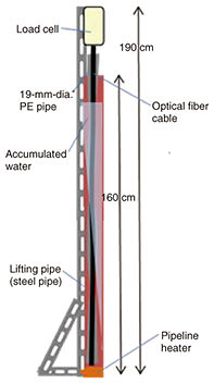
3. Verification of the impact of freezing and thawingConsidering that ice lumps were confirmed near the top-end of the lifting pipe, we verified the impact of freezing and thawing of accumulated water on the optical cable and PE pipe. (1) Freezing and thawing of accumulated water To verify this impact, we constructed an experimental apparatus that simulates a lifting pipe in a large thermostatic room. As shown in Fig. 3, a steel pipe, which is made of the same material as an actual lifting pipe, was installed in a thermostatic room, and an optical cable, PE pipe, and water were inserted into the steel pipe to simulate the field condition.
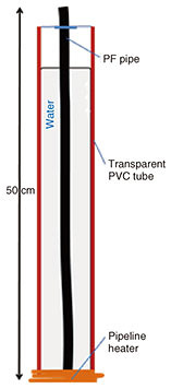
The temperature of the thermostatic room was repeatedly set between −15 and +10°C in accordance with the climatic environment at the field. We assumed that the lowest part of the lifting pipe would not freeze because it is in the underground section. Thus, we used a pipeline heater*1 to reproduce this condition. A load cell was attached to the top of the optical fiber cable to measure the stress applied in the vertical direction by the freezing and expansion of the accumulated water. The optical fiber cable and PE pipe rose by 1.7 cm when the water in most of the steel pipe (except for the heater section) froze and thawed. The measurements on the load cell showed that the tip of the optical fiber cable was pushed by an upward force of up to about 780 N during the thawing of the accumulated water. Note that the strong upward force was not recorded at the lowest temperature of −15°C, that is, it was always recorded during the subsequent temperature increase. These results indicate that the freezing and thawing of the accumulated water in the lifting pipe generated an upward force on the optical fiber cable and PE pipe. Since the optical fiber cable outside the lifting pipe was pushed upward, we assumed that the compressed and expanded damage (Fig. 2(d)) to the sheath of the upper part of the optical fiber cable was caused by the repeated upward force exerted toward the fixture point (stainless-steel band) on the utility pole. (2) Observation of phenomena inside a lifting pipe Considering the results described in verification (1), we observed the changes in the water and their impact on the cable and PE pipe. The results are as follows. We inserted a plastic flexible (PF) pipe (which simulates an optical fiber cable) into a transparent polyvinyl chloride (PVC) tube (which simulates the lifting pipe). The experimental apparatus was filled with water and placed in a thermostatic room. We observed the phenomena inside the pipe, when temperature in the surrounding area repeatedly changed between –15 to 10°C, that is, water in the lifting pipe froze and thawed, repeatedly (Fig. 4).
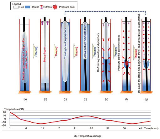
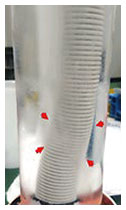
The set temperature in the thermostatic room was assumed to be in the range of −15 to +10°C, as in verification (1). To simulate the unfrozen part (underground section) of the lifting pipe, a pipeline heater was installed at the bottom of the transparent PVC tube. The upper end of the PF pipe was fixed with a stainless-steel band at the opening of the PVC tube in the same manner as the optical fiber cable is fixed to the utility pole with a stainless-steel band. The results of repeated freezing and thawing are shown in Figs. 5(a) to (h) and summarized as follows. Result 1: Freezing progressed from the top of the PVC tube to the sides, bottom, and center, and most of the tube froze except for the area near the heater. The water surface (Fig. 5(a)) also rose by about 2.5 cm (Fig. 5(b)). Result 2: When the temperature was gradually increased from the frozen state, thawing progressed from the outside of the PF pipe, but ice remained from the center to the upper part of the pipe, wrapping around it (Fig. 5(d)). Result 3: When the water was re-frozen from the state described in Result 2*2, new ice was formed in addition to the remaining ice from the center to the top of the PF pipe, and the water surface rose again (Figs. 5(e) and (f)). In the unfrozen area between the remaining ice and newly formed ice, the PF pipe was deformed as if it had been crushed under pressure (Fig. 5(f) and Fig. 6).
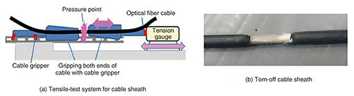
4. DiscussionFrom the results of the two verifications described above, it is conceivable that the optical fiber cable installed in a lifting pipe is pushed up during the process by which rainwater infiltrates the pipe and the accumulated water repeats freezing and thawing for the following three reasons: (i) the ice remaining near the top and center of the pipe solidifies when surrounding the cable; (ii) the internal pressure of the unfrozen part increases due to the expansion pressure caused by the subsequent new freezing from the periphery (Figs. 5(d) to (f)); and (iii) as the temperature increases, the surrounding ice begins to melt, and the optical fiber cable is pushed up from the pressure point when its internal pressure is released while being held by the ice (Fig. 5(g)). We thus conclude that due to the repetition of freezing and thawing, the optical fiber cable inside the lifting pipe pushes upward and exerts a crushing force on the cable section outside the lifting pipe toward the point at which it is fixed to the utility pole. The strong upward force mentioned in verification (1) did not occur at the lowest temperature but during temperature increase. The reason is that the pressure applied to the inside of the lifting pipe was released by partial thawing and pushed upward to the top of the pipe, namely, along its escape route. 5. Reproduction of damage to cable sheathAs mentioned in verification (1), the optical fiber cable was pushed up with a force of about 780 N during thawing after the water in the steel pipe froze. To verify whether the tensile force due to repeated freezing and thawing during winter would damage the outer sheath of the optical fiber cable, we conducted a test in which one end of the cable was fixed and the other end was pulled with a force of 780 N (Fig. 7(a)). The test was carried out by repeatedly applying then releasing the tension under the environment in which freezing and thawing are repeated. Applying and releasing tension, the outer sheath was damaged on the 35th repetition, and gradually torn off by further repetition (Fig. 7(b)).
6. ConclusionWe investigated the damage to an optical fiber cable and PE pipe in a lifting pipe installed in cold regions. The experimental results indicate that repeated freezing and thawing of accumulated water, which somehow enters the lifting pipe, causes pressure to build up inside the pipe as the water transforms (and expands) to ice, which in turn exerts a force that pushes up the optical fiber cable and deforms it during thawing. They also indicate that the repeated freezing and thawing tears the outer sheath of the optical fiber cable and PE pipe, eventually leading to failure of the optical fiber cable. |
|||||