 |
|||||||||||||||||||||||||
|
|
|||||||||||||||||||||||||
|
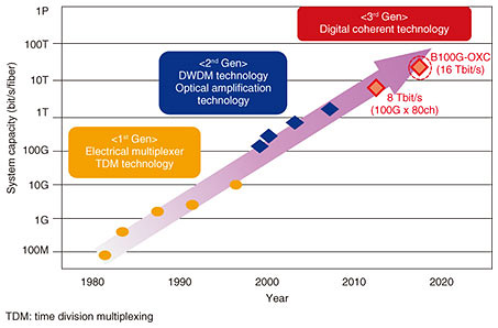
Regular Articles Vol. 19, No. 11, pp. 59–64, Nov. 2021. https://doi.org/10.53829/ntr202111ra2 Development of Beyond 100G Optical Cross Connect (B100G-OXC) SystemAbstractThe rapid increase in Internet traffic is expected due to the spread of network services such as 5G (fifth-generation mobile communication), Internet of Things, and cloud. To economically expand the capacity in the core network of the NTT Group, NTT Network Innovation Center developed the Beyond 100G Optical Cross Connect (B100G-OXC) system, which enables beyond 100-Gbit/s per wavelength optical transmission. This article gives an overview of this system. Keywords: optical transport, DWDM, multi-level modulation 1. Capacity enhancement in the core networkNTT has expanded the capacity of optical transport systems to build both an efficient and economical optical transport network to address the constant increase in communication traffic in the core network, as shown in Fig. 1. In the current optical transport system, which has been deployed, we achieved a maximum of 8-Tbit/s capacity by multiplexing 80 channels of an optical signal with 100-Gbit/s per wavelength through the use of digital coherent technology*1. To further enhance system capacity, we developed the Beyond 100G Optical Cross Connect (B100G-OXC) system as a higher-capacity optical transport system by increasing the signal speed.
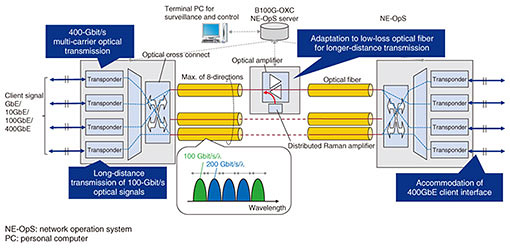
2. Technical features of B100G-OXC systemThe system configuration of the B100G-OXC system is shown in Fig. 2. It is an optical transport system based on dense wavelength-division multiplexing (DWDM) and digital coherent technology (DWDM is the technology to transmit multiple wavelengths in a single fiber).
The B100G-OXC system is also called ROADM (reconfigurable optical add/drop multiplexer) since it can configure optical nodes as “add,” “drop,” or “through” for any arbitrary optical path in a maximum of eight directions. The main technical features of the B100G-OXC system are as follows:
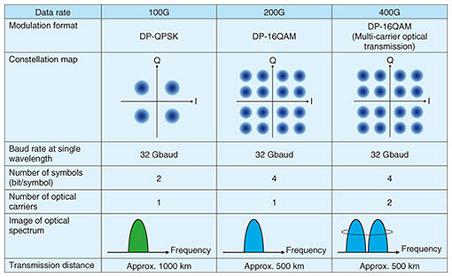
2.1 400-Gbit/s multi-carrier optical transmissionThere are several ways to enhance capacity. One is to increase the number of wavelengths for multiplexing, and the other is to increase the signal speed of the optical channel per wavelength. In addition, there are mainly three ways to increase the signal speed of an optical channel [1]: 1. Increase the rate of modulation 2. Increase the degree of the multiple modulation/demodulation scheme 3. Enable multi-carrier optical transmission With the B100G-OXC system, we increased the transmission rate per wavelength from 100 to 200 Gbit/s by changing the modulation scheme from dual polarization-quadrature phase shift keying (DP-QPSK), which is used in the conventional 100-Gbit/s-based optical system, to DP-16 quadrature amplitude modulation (QAM), maintaining the baud rate at 32 Gbaud, which is that of the conventional system (Table 1). We also achieved maximum 500-km transmission at a 400-Gbit/s data rate with no regeneration by using 2 x 200-Gbit/s optical signals.
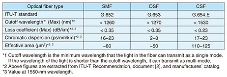
2.2 Long-distance transmission of 100-Gbit/s optical signalsIn the core network, long-distance transmission is as critical as capacity enhancement in terms of building a network more economically. There is generally a trade-off between increasing the transmission rate (higher-capacity transmission) and transmission distance. Although we can achieve a higher rate of transmission by increasing the degree of the multi-level modulation scheme (for example, from DP-QPSK to DP-16QAM), transmission distance can be decreased. In the B100G-OXC system, we adopted DP-QPSK, which is the same modulation scheme as in the conventional 100-Gbit/s-based optical transport system to achieve 1000-km transmission without regeneration, which is almost double that of the conventional system. The B100G-OXC system also enables us to change the mode of the modulation scheme as well as transmission rate through software, so it is possible for us to select the optimum type of modulation more flexibly on the basis of the target distance of the route. 2.3 Adaptation to low-loss optical fiber for longer-distance transmissionWe attribute 400-Gbit/s multi-carrier 500-km transmission to the fact that we adapted the B100G-OXC system to the new cutoff shifted fiber (CSF, complied with ITU-T*2 G.654.E) as well as single mode fiber (SMF, compliant with ITU-T G.652) or dispersion shifted fiber (DSF, compliant with ITU-T G.653). CSF offers a lower loss profile than that of the other types of fibers for longer transmission. It also secures a larger effective area*3 by expanding the diameter of the optical fiber core, which allows us to suppress the degradation of optical signals due to nonlinear effects that can occur during the transmission through the fiber. As a result, we can achieve longer transmission distance. The general optical characteristics of SMF, DSF, and CSF are listed in Table 2 [2].
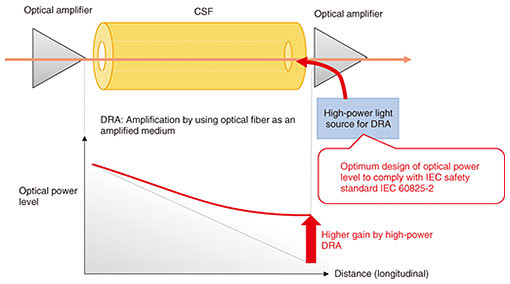
We also achieved high-power distributed Raman amplification (DRA) in the B100G-OXC system as a key technology for longer-distance transmission, as shown in Fig. 3. DRA amplifies optical signals by using optical fiber as an amplified medium, so its gain characteristic depends on the fiber characteristics. Initially lower gain of DRA was assumed for CSF since it has a relatively larger core than those of other fibers. We then achieved high-power DRA to obtain sufficient gain even under CSF. Safety design is also important for long-term operation because we need to handle a high-power excitation light source, which has around 100 mW of output power. With the B100G-OXC system, we determined the optimum condition for the excitation light source for DRA to achieve maximum transmission performance while maintaining safety by complying with IEC*4 60825-2, which is the international standard on the safety of optical-fiber communication systems.
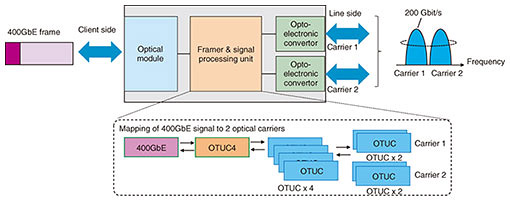
2.4 Accommodation of 400GbE client interfaceIn the B100G-OXC system, we achieved the accommodation of the 400GbE*5 client interface in combination with 400-Gbit/s multi-carrier optical transmission. This allows us to connect with new large-scale routers or Layer 2 switches. The 400GbE interface has been standardized and is now widely used mainly in datacenters. Figure 4 shows a schematic of how 400GbE is transmitted. The incoming 400GbE signal is mapped onto 4 x OTUC*6 frames in the framer and signal processing unit inside the transponder (transceiver). Each OTUC frame has a 100-Gbit/s bit rate. Two OTUC frames are modulated in a single optical carrier, which has a 200-Gbit/s rate, then 400GbE data are transmitted using 2 x 200-Gbit/s optical carriers [3].
3. Conclusion and future perspectivesWe achieved both high-capacity and longer-distance transmission to build a core transport network more economically. NTT is now researching and developing the All-Photonics Network [4], which is one of the innovative optical transport platforms to implement IOWN (Innovative Optical and Wireless Network). We are aiming to further increase the speed of optical signals per wavelength such as 400 Gbit/s or 1 Tbit/s. We will also target furthering high-capacity transmission by using multi-band transmission [5] to expand the transmission-wavelength range or using space-division multiplexing technology such as multi-core fibers [6]. We will continue to work on further improving optical transport systems and expanding transmission capacity. References
|
|||||||||||||||||||||||||

