|
|
|
|
|
|
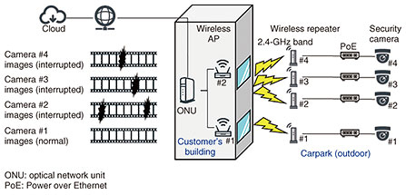
Practical Field Information about Telecommunication Technologies Vol. 19, No. 12, pp. 93–96, Dec. 2021. https://doi.org/10.53829/ntr202112pf1 Case Studies of Communication Problems with Video Transmission Systems Using Wireless LANsAbstractThis article introduces recent problems that have occurred when using wireless local area networks for video transmission and solution to these problems. This is the sixty-seventh article in a series on telecommunication technologies. Keywords: wireless LAN, channel interference, video transmission, low-emissivity glass  1. IntroductionInternet access using wireless local area networks (LANs) has become available both for indoors and outdoors. We use wireless LANs for a wide variety of purposes, which include not only accessing websites, sending and receiving emails, and social networking but also video distribution. However, when designing and constructing wireless LAN systems for video transmission such as to display security-camera images or the screen of a personal computer (PC) on a large display, it is necessary to take into account data delays and losses. This article introduces two recent problems that have occurred when using wireless LANs for video transmission and solutions of these problems. 2. Problem case with security-camera system2.1 Equipment configuration and problem situationA problem with a security-camera system using a wireless LAN was reported by our customer. The equipment configuration is shown in Fig. 1. Two wireless-LAN access points (wireless APs) were installed near the windows of a two-story office building. One of these was on the first floor and the other was on the second floor. These wireless APs were connected to four security cameras via wireless repeaters. These cameras and wireless repeaters were installed on four poles for outdoor lighting. The images from the cameras were stored in the cloud via the wireless LAN and Internet. The customer reported that video streams from three cameras, which were connected to the wireless APs on the second floor, were frequently interrupted.
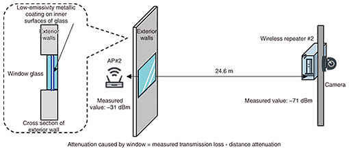
The wireless LAN used the 2.4-GHz band, which is generally considered to be affected by interference. Accordingly, the maintenance engineer switched from that band to the 5-GHz band (W56), which is less affected by interference and generally used outdoors. However, interruptions were not resolved, so the Technical Assistance and Support Center (TASC) was asked to investigate the problem. 2.2 Investigation of causeWe set the frequency used for the wireless LAN to the 2.4-GHz band and measured the radio-wave environment and the received signal strength. (1) Investigation of radio-wave environment We used a wireless LAN tester, which was developed by TASC, to measure radio waves in the 2.4-GHz band and found no interference or other wireless-LAN waves that could cause radio-wave interference. (2) Measurement of received signal strength Using a measuring instrument that can measure the radio-wave strength of devices, we measured the received signal strength of the radio waves near the wireless APs and wireless repeaters. The received signal strength of the radio wave for downlink transmitted from a wireless AP near a wireless repeater was less than –60 dBm, and that for uplink transmitted from a wireless repeater near the wireless AP was very weak, ranging from –74 to –100 dBm, which was the measurement limit. The measured radio-wave strength for downlink near the wireless APs and wireless repeaters was –31 and –71 dBm, as shown in Fig. 2. The results indicate that the transmission loss between a wireless AP and wireless repeater was about 40 dB. The theoretical value of distance attenuation calculated from the distance of 24.6 m between the wireless AP and wireless repeater is 28 dB (≒ 20log (24.6 m)); therefore, attenuation of 12 dB (about 1/20) was caused by the window glass in the building. The window was a type of double glazing and the inner surfaces of the glass were covered with a low-emissivity metal coating to reduce radiant heat from the sun.
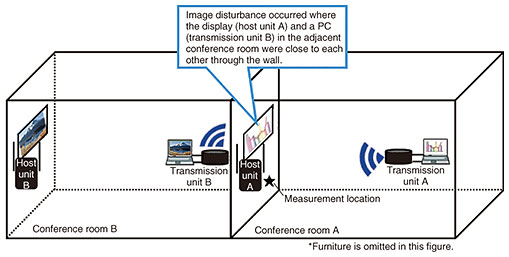
2.3 Cause of problemFrom our investigation, it was presumed that the large attenuation caused by the low-emissivity glass interrupted the video streams from the security cameras. The radio waves for uplink from the wireless repeater were significantly weakened, so the communication between the wireless APs and wireless repeaters probably become unstable. 2.4 SolutionIn this case, by moving the wireless APs away from the low-emissivity window glass, which prevents the transmission of radio waves, it is possible to increase the amount of radio-wave transmission through the wall other than the glass. When we moved the wireless APs, the received signal strength between the wireless APs and each wireless repeater increased and improved radio-wave throughput, eliminating video interruptions. 3. Problem case with video-image-transferring system3.1 Equipment configuration and problem situationA problem with a security-camera system using a wireless LAN was reported from our customer. The equipment configuration is shown in Fig. 3. A wireless display adapter (WDA), which is used to display the screen of a PC on a large display via a wireless LAN, has two units. Its host unit is connected to the display and its transmission unit is connected to the PC. At the customer’s premises, many WDAs were installed in conference rooms and meeting spaces. The WDAs used the 5-GHz band of wireless LAN, and channel bonding was used to ensure the 40-Mbit/s bandwidth, which is required for video transmission.
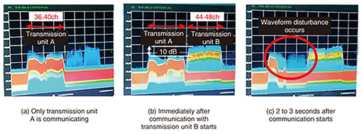
The 5-GHz-band wireless LAN has a dynamic frequency selection (DFS) function that automatically switches the channel to be used if radar waves, etc. are received. In this equipment configuration, W52, a frequency band that is not used by radar waves, was used to avoid communication interruption due to channel switching by DFS. This band was also divided into two channel groups (36/40ch and 44/48ch) to avoid inter-channel interference. Despite these attempts, the video images displayed on the large display were disrupted in certain areas. 3.2 Investigation of cause(1) Investigation of radio-wave environment We used a spectrum analyzer to measure the radio-wave environment in the 5-GHz band, and no radio waves other than those of WDAs were measured. (2) Investigation of transmission-waveform spectrum We measured the transmission-waveform spectrum near host unit A when video disturbance occurred (Fig. 4).
The measurement results indicate that transmission units A and B used different channel groups and that at the measurement location shown in Fig. 3, the received signal strength from transmission unit B was about 10 dB higher than that from transmission unit A. They also indicate that two to three seconds after transmission unit B started communication, the transmission waveform from transmission unit A was disrupted (Fig. 4(c)) and, simultaneously, the video image was disrupted. 3.3 Cause of problemIt was presumed that this disturbance was caused by the radio wave from transmission unit B, which was about 10 dB higher than that from transmission unit A, reached host unit A, although conference rooms A and B were separated by a wall. The radio wave from transmission unit B reached the host unit A; therefore, the communication between transmission unit A and host unit A was affected. This disturbance is presumed due to adjacent-channel interference, which is caused by the arrival of strong radio waves on the adjacent channel. 3.4 SolutionThe basic solution against problems like this case is to improve the radio-wave environment. To improve such an environment, it is necessary to ensure the distance between the wireless-LAN devices, to prevent radio-wave interference between the wireless-LAN devices by installing sheets of radio-wave shielding, to shorten the distance between the host and transmission units or not to obstruct the line of sight between the host and transmission units. However, it was difficult to implement the above-mentioned solution in this case; therefore, we set up the same communication channel for units A and for units B and controlled the transmission timing temporally. It became possible to stabilize the communication in the wireless section and eliminate video disturbance. It should be noted that when the same channel is used for multiple wireless devices, the transmission rate will be divided in proportion to the number of devices; therefore, it is necessary to verify operation before installation of the devices to ensure that the bandwidth required for video transmission can be secured. 4. ConclusionRecent problem cases with video transmission systems using wireless LANs and their solutions were introduced in this article. TASC develops tools that can be used in the field to analyze and identify the cause of problems in wireless-LAN and wireless-based systems. The EMC Engineering group in TASC is continuously engaging in technical support to the field regarding problems caused by lightning, malfunction due to electromagnetic phenomena, interference of radio waves, induction from power line, and so on, to ensure reliability of telecommunication services. |