 |
|||||||||||||||||||||||||||||||||||
|
|
|||||||||||||||||||||||||||||||||||
|
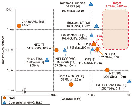
Regular Articles Vol. 20, No. 3, pp. 36–45, Mar. 2022. https://doi.org/10.53829/ntr202203ra1 Experimental Evaluation of High-capacity Wireless Transmission Using Orbital Angular Momentum Multiplexing TechnologyAbstractWe are researching and developing technology to achieve terabit-class wireless transmission toward six-generation wireless systems. In this article, we present experimental evaluations of high-capacity wireless transmission using orbital angular momentum (OAM) multiplexing on a 40-GHz frequency band with a bandwidth of 1.5 GHz at distances of 100 and 200 m. Our OAM antennas have two uniform circular arrays (UCAs) with the same diameter using different linear polarizations and Butler matrices, which are analog devices for generating and separating OAM modes. OAM beams are generated using a Butler matrix, which is an analog radio-frequency circuit, and radiated from the UCAs. We implemented an OAM multiplexing transmitter (Tx) and receiver (Rx) on the 40-GHz band. The Tx and Rx can generate and separate seven OAM modes (0, ±1, ±2, ±3) and two polarizations (vertical and horizontal), which is a total of 15 streams including the center antenna element to transmit OAM mode 0. Each channel carries a 1.5-Gbaud signal. We experimentally evaluated the transmission capacity at distances of 100 and 200 m. The results indicate successful wireless data transmission of 137 Gbit/s at a distance of 100 m and 117 Gbit/s at a distance of 200 m. Keywords: orbital angular momentum (OAM), point-to-point, line-of-sight, uniform circular array, 40-GHz band 1. IntroductionThe demand for achieving high-capacity wireless transmission is increasing due to exponentially increasing data traffic toward six-generation (6G) wireless systems [1]. The use of wireless transmission is expected to increase in all fields including connected cars, virtual reality/augmented reality, three-dimensional cameras, and high-definition video transmission. Considering such an increase, it is anticipated that the hundreds-of-gigabit level to terabit level wireless transmission will be necessary in the 2030s [2–4]. There have been many reports on high-capacity wireless transmission in orbital angular momentum (OAM) and multiple-input multiple-output (MIMO)/single-input single-output (SISO) multiplexing [5–17], as shown in Fig. 1. We provide a summary of these reports below. There have been reports on experiments over 100 Gbit/s in short distances (<10 m) in laboratory environments, and approximately 100 Gbit/s in outdoor environments (≥100 m). In terms of transmission capacity, 1.056-Tbit/s wireless transmission over 3.6 m was reported by GTEC, Fudan University using 4×4 MIMO on D-band [5]. In terms of transmission distance, Northrop Grumman, DARPA [6] reported 100-Gbit/s wireless transmission (total rate of transmission and reception) at a distance of 20 km. The result from 5G commercial networks was the 8-Gbit/s transmissions reported by Nokia, Qualcomm, and Elisa [7]. Regarding OAM multiplexing, 32-Gbit/s transmission on the 60-GHz band over 2.5-m distance was reported by University of Southern California [8], and 14.8-Gbit/s transmission on the 150-GHz band over 100 m using real-time signal processing was reported by NEC [9]. Considering beyond 5G and 6G wireless communication, we set our target to 1 Tbit/s and over 100-m transmission.
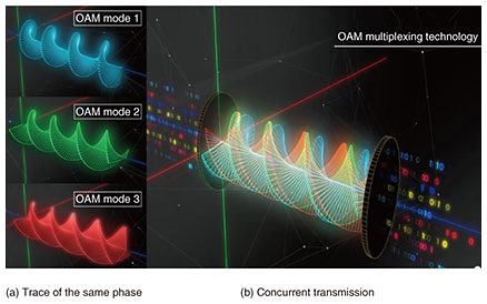
To achieve such terabit-class wireless transmission, we are researching OAM multiplexing transmission technology as a new spatial multiplexing technology that enables high-capacity wireless transmission. We previously reported on experiments of over 200-Gbit/s transmission using OAM-MIMO multiplexing on the 28-GHz band at a distance of 10 m in a shielded room [10]. We further achieved wireless data transmission of 137 Gbit/s at a distance of 100 m and 117 Gbit/s at a distance of 200 m [11] using OAM multiplexing on the 40-GHz band. The remainder of this article reports on the principle of OAM multiplexing and our recent research. 2. OAM multiplexing technology2.1 PrincipleOAM is a physical property of electro-magnetic waves characterized by a helical phase front in the propagation direction. Since these characteristics can be used to create multiple orthogonal channels, wireless communication using OAM can increase radio-spectrum efficiency and expand the capacity of the scarce radio spectrum. The number of phase rotations is called an OAM mode. Different data signals can be transmitted at the same time by transmitting different signals using radio waves having different OAM modes [8]. Given an electromagnetic wave having this OAM property, the trace of the same phase takes on a helical shape in the direction of propagation (Fig. 2). For example, Figure 2(a) illustrates the trance of the same phase in OAM modes 1, 2, and 3. Radio waves having this OAM property cannot be received without a receiver (Rx) having the same number of phase rotations at the time of transmission. For this reason, if multiple radio waves having different OAM modes are superposed, they can eventually be separated without mutual interference as long as an Rx is prepared that can receive radio beams with the same phase rotations corresponding to each OAM mode. Figure 2(b) shows an example in which different signals are put on OAM modes 1, 2, and 3 and transmitted simultaneously. Technology for transmitting multiple data signals using this feature is called OAM multiplexing transmission technology.
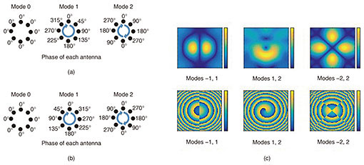
2.2 Generation and separationTo generate a beam carrying the OAM mode n (L = n), antenna elements are connected with phase shifters that make n × 360 degrees of rotations. Figure 3(a) shows an example of beam generations of OAM modes 0, 1, and 2 using a uniform circular array (UCA) consisting of 8 antenna elements. Note that concurrent transmission of multiple OAM modes can be achieved by superposing multiple OAM signals, as in Fig. 3(c). The separation of beams carrying OAM modes can be done in a similar manner as generation using antenna elements connected with phase shifters that make opposite direction of rotations. As far as the number of antenna elements are larger than 2n, n × 360 degrees of rotations are orthogonal one another. Therefore, the separation of each OAM mode from a mixed OAM mode signal can be done without aliasing. Figure 3(b) shows an example of the phase of each antenna element corresponding to the example above.
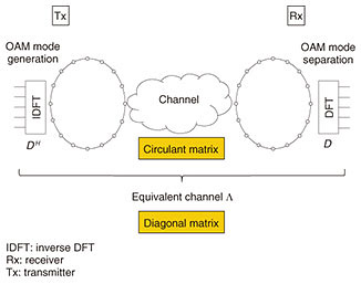
2.3 Transmission and receptionThe beams with different OAM modes can be approximately generated or separated simultaneously using a UCA with a discrete Fourier transform (DFT). They are orthogonal as long as they propagate coaxially. Mathematically, the channel between UCAs is a circulant matrix, so the channel can be diagonalized using a DFT matrix as the singular value decomposition (SVD) method, meaning oppositely arranged transmitting and receiving UCAs can create several isolated channels regardless of the propagation distance. Theoretically, the OAM has an infinite depth of field, but the discretization of space sampling limits the maximum number of available OAM modes when using a UCA and DFT processor. The maximum number is equal to the number of antenna elements in a UCA. When using UCAs for transmitting and receiving antennas, the beam propagation with OAM modes can be analyzed using the standard narrow band MIMO theory. We now discuss the theoretical background of an OAM multiplexing system with UCAs. Figure 4 shows a schematic chart of OAM multiplexing transmission. When UCAs are placed opposite each other, the antenna-array configuration is axisymmetric so that the channel matrix becomes circulant. When the number of antenna elements in a UCA is defined as n, the circulant matrix is diagonalized using the n × n DFT matrix
where l denotes OAM mode corresponding to the yth eigenvector, H and Σ denote the channel matrix between the receiving and transmitting UCAs and diagonal matrix, respectively, and Λ denotes the equivalent channel matrix including DFT processing, as shown in Fig. 4.
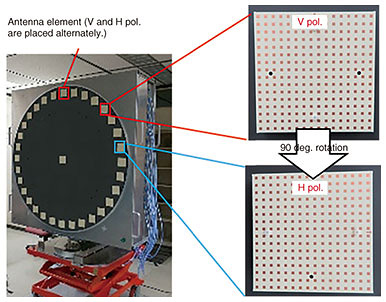
One of the strengths of OAM multiplexing is that it only requires static processing and DFT, so we can use analog devices for OAM-mode generation and separation without digital signal processing. A Butler matrix is an analog circuit that can process DFT calculations with hybrid circuits and phase shifters, so we used it for OAM-mode generation and separation in our system [11, 17]. 3. Transceiver designWe designed a 40-GHz-band OAM multiplexing transceiver to conduct outdoor experiments. Figure 5 shows this transceiver and its antenna elements. The diameter of the UCA is 120 cm, and a total of 33 antenna elements (16 elements each for vertical (V) and horizontal (H) polarization UCA and the center) are placed on the circumference. The antenna size depends on the frequency, as shown in Table 1. The size can be reduced when higher frequency bands are used. The gain of the antenna element is 25 dBi. This antenna element can radiate V or H polarization by rotating 90 degrees. One antenna element is placed on the center of a UCA to transmit mode 0 at the singular points of the OAM mode.
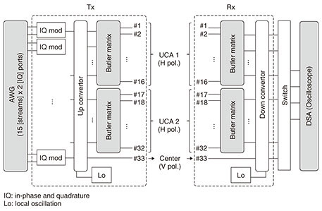
Figure 6 shows a block diagram of the OAM-transmission experiment. Baseband (BB) signal waveforms generated by Matrix Laboratory were input to the transmitter (Tx) using arbitrary waveform generators (AWGs). Analog BB signals were up-converted to radio frequencies (RFs) of 39.5 to 41 GHz signals in the Tx. Finally, 7 OAM modes signals were generated and multiplexed using Butler matrices in each polarization and transmitted from the 16 antenna elements. The mode isolation of these Butler matrices was over 15 dB [17]. We designed 7×16 Butler matrix working on the 40-GHz band for DFT processing to generate and separate seven OAM modes (OAM modes 0, ±1, ±2, ±3). We first designed 8×16 Butler matrices and terminated a port for OAM mode 4. By using these Butler matrices, we can reduce RF chains because we just prepare the RF chains for the OAM modes used to multiplex rather than for all antenna elements.
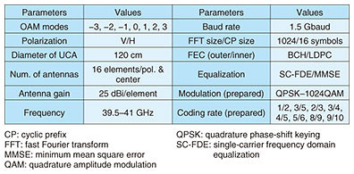
The OAM beams were propagated to the Rx. The Rx was embedded with a variable attenuator, which made it possible to adjust the received signal level appropriately even if the received power varies with the transmission distance. The received signals were separated for each OAM mode signal by using the Butler matrices and down-converted to intermediate frequency (IF) signals. Finally, the digital serial analyzer (DSA) stored and saved the IF signals as waveform data. The saved waveforms were demodulated by MATLAB off-line signal processing, and we evaluated the transmission capacity. We coded the multiplexed data streams with a low-density parity-check (LDPC) code and Bose-Chaudhuri-Hocquenghem (BCH) code with a frame length of 64,800 bits on the basis of the Digital Video Broadcasting - Satellite - Second Generation (DVB-S2) standard used as forward error collection (FEC). We applied an adaptive modulation and coding algorithm with which the modulation order and adaptively determined the coding rate depending on the signal-to-noise ratios (SNRs). We prepared error-free SNR ranges in advance as a table for each modulation order and coding rate. We summarize the system specifications of the OAM transmission in Table 2.
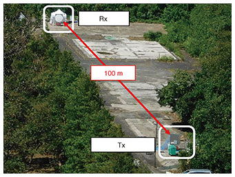
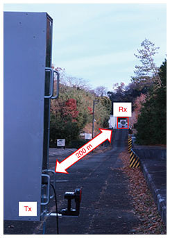
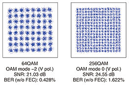
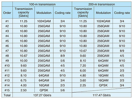
4. Experimental evaluations4.1 Experimental setupTable 2 lists the specific parameters of our experimental setup. We multiplexed 15 data streams using 7 OAM modes and 2 UCAs with different linear polarizations in both transmitting and receiving antennas. We then designed antenna elements in the UCAs, which were patch antenna arrays with an antenna gain of 25 dBi, as shown in Fig. 5. The isolation between different linear polarizations of the antenna elements was more than 30 dB on average across the whole bandwidth. In accordance with the relationship between effective bits in a symbol and SNR of our digital signal processing and the symbol rate of 1.5 GHz, roughly a 20-dB SNR on average of 15 data streams is enough to obtain more than 100 Gbit/s. The amount of transmitting power and antenna gains was roughly 53 dB. The channel gain was then roughly –90 dB, and the noise floor including the receiver noise figure was −67.7 dBm. We thus determined that our experimental system was able to obtain more than a 20-dB SNR on average across all of OAM modes. 4.2 Experimental resultsWe conducted outdoor wireless transmission experiments at distances of 100 and 200 m. Each distance was a line-of-sight environment, as shown in Figs. 7 and 8, respectively. The alignment between the Tx and Rx was conducted using a laser rangefinder placed at the corner of the antenna. Error-free transmission with channel coding was 137.3 Gbit/s with 15 streams at a distance of 100 m. The spectral efficiency was 91.5 bit/s/Hz. The 200-m error-free transmission with channel coding was 117.5 Gbit/s with 14 streams. Figure 9 shows the representative measured constellations of 64 quadrature amplitude modulation (QAM) and 256 QAM. The SNRs were 21.03 and 24.55 dB, and the bit error rates (BERs) without FEC were 0.428 and 1.622%. We transmitted a few data frames and confirmed reproducibility. The spectral efficiency was 78.3 bit/s/Hz. The multiplex number of 14 at 200 m was due to the modified water-filling-power allocation and providing a margin for determining modulation and coding rates. Table 3 shows the transmission capacity, modulation, and coding rate of each stream. They are listed in descending order of transmission capacity, that is, the order of the receiving SNR. The modulations used were from quadrature phase-shift keying (QPSK) to 1024 QAM for each stream, and transmission rates were up to 11.25 Gbit/s. We previously reported the achievement of 119.7 Gbit/s transmission at a distance of 100 m and showed that similar capacity can be achieved at a distance of 200 m.
5. Discussion and conclusionWe designed transmitting and receiving antennas of OAM multiplexing for over 100-Gbit/s wireless transmission at a distance of 100 m. Our antennas have two UCAs with 16 antenna elements for different linear polarizations, and Butler matrices for OAM-mode generation and separation. Therefore, we could use two orthogonal bases of seven OAM modes (OAM mode 0, ±1, ±2, ±3) and dual polarization. An antenna element of V-pol. was arranged at the center of each antenna. The radio wave transmitted from the center antenna element was OAM mode 0, which provided an additional data stream for multiplexing. Note that there were two data streams in OAM mode 0 of V-pol., which were not orthogonal to each other. However, they had different eigenvectors for the radius direction, so they could be isolated by traditional MIMO-based digital signal processing. We conducted a transmission experiment using OAM multiplexing in the field at distances of 100 and 200 m. We confirmed that the transmission capacity of over 100 Gbit/s can be achieved even at 200 m. We implemented offline signal processing including transmit precoding based on SVD and the OAM multiplexing Tx and Rx on the 40-GHz band. This Tx and Rx can generate and separate seven OAM modes (−3, −2, −1, 0, 1, 2, 3) by using Butler matrices for each polarization. Each channel carries a 1.5-Gbaud signal. The results indicate that wireless data transmissions of 137.3 Gbit/s at a distance of 100 m and 117.5 Gbit/s at a distance of 200 m were successful. The spectral efficiency was respectively 91.5 and 78.3 bit/s/Hz at 100 and 200 m. References
|
|||||||||||||||||||||||||||||||||||

