 |
|||||||||||
|
|
|||||||||||
|
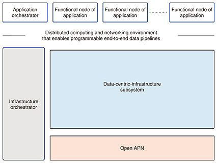
Feature Articles: Development of IOWN with Global Partners Vol. 20, No. 5, pp. 24–31, May 2022. https://doi.org/10.53829/ntr202205fa3 Data-centric-infrastructure Functional ArchitectureAbstractSociety is changing at a rapid pace due to technical innovations in Internet technologies and cloud computing. In the near future, ever-more refined artificial-intelligence applications are expected, working on ever-larger data sets. Implementing such applications requires increasing the computational capacity available to the providers of such newly emerging services. However, energy consumption of such services must be reduced to achieve ESG (environmental, social, and governance) and the sustainable development goals. To fulfill both of these objectives at the same time, a drastic rethink of computing infrastructure is required. With this in mind, the IOWN Global Forum is creating the data-centric-infrastructure (DCI) functional architecture. This article gives an overview of the first DCI functional architecture reference document about this next-generation computing foundation. Keywords: IOWN, data-centric, DCI 1. The data-centric-infrastructure computing platformThe IOWN Global Forum (IOWN GF) is specifying a holistic architecture that comprises both networking and computing, as illustrated in Fig. 1 and published the first data-centric-infrastructure (DCI) functional architecture reference document in January 2022 [1]. Within this overall architecture, the DCI subsystem provides computing and networking services to various types of applications. The DCI is specified with the assumption that a high-performance optical network, the Open All-Photonic Network (Open APN) [2], is available for mid- and long-range data transfers. The goal with the DCI is to provide a quality of service (QoS)-managed execution environment for applications making use of multiple types of computing resources, such as central processing units (CPUs), memory, field-programmable gate arrays (FPGAs), and graphics processing units (GPUs), that are placed in a distributed fashion. These computing resources that the DCI will include comprise both generic computation elements and accelerators for artificial intelligence (AI) processing. The DCI makes computing resources available to applications via application programming interfaces (APIs) accommodating the needs of service providers.
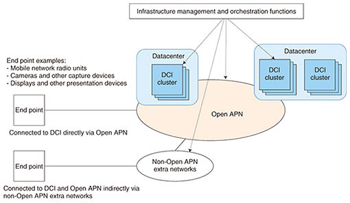
2. Technology gaps in current computing-platform architecturesIOWN GF conducted a gap analysis to identify the technological innovations required for future use cases. The following gaps that need to be addressed were identified. 2.1 Scalability issuesDifferent applications have different requirements regarding computing resources, memory, and input/output mechanisms. To appropriately serve a wide variety of applications, various computing resources meeting the requirements of each application need to be allocated without waste. However, classic, rack-oriented computing platforms are generally not considered able to efficiently combine resources located in different servers. 2.2 Performance issuesDifferent types of applications have different requirements. Some applications have stringent requirements toward latency and jitter. Classic servers are typically connected using networks designed to provide best-effort services. Such networks do not satisfy the requirements of many future applications. Therefore, the stringent requirements of future applications need to be taken into account from the beginning when designing future computing and network architectures. 2.3 Energy consumption issuesThis issue is related to the scalability issue above. Multiple types of computing resources must be scheduled to execute work without idle time since idle resources will only consume energy without executing useful functions. Therefore, IOWN GF is developing an architecture that maximizes resource utilization while using energy more effectively. 3. Design goalsOn the basis of the gap analysis outlined above, the following design goals were identified for the DCI: (1) Provide scalability in an environment ranging from user devices over edge networks and clouds to other clouds. (2) Enable the use of computing resources other than CPUs. (3) Implement data pipelines on the basis of a high-speed optical network to enable efficient data transfers between applications of a use case. (4) Enable sharing among accelerators, such as GPUs and FPGAs, without having to execute redundant data transfers. (5) Simultaneously support different QoS objectives such as high bandwidth, bandwidth reservation, low latency, and low jitter. (6) Provide a gateway function to exchange data between the classic Internet protocol (IP)-based network domain and non-IP-based network domain. The DCI is being designed by taking into account these six goals. The relations between the DCI subsystem, Open APN, and pre-existing networks, as the resulting architecture, are illustrated in Fig. 2. End points, such as mobile network radio units or remote sensors, may connect to DCI clusters either directly via Open APN or indirectly using a network outside Open APN (non-Open APN extra network) as an intermediate step.
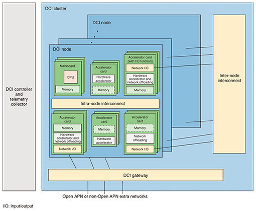
4. DCI clusterThe DCI architecture defines logical service nodes (LSNs). Following the DCI design goals, LSNs are a means to provide execution environments comprising, e.g., computing and networking resources to applications in appropriate units. LSNs provide users with resources that are logically separated at the hardware level. To provide such LSNs, multiple computing and networking resources must be appropriately selected and combined. The DCI architecture defines that DCI clusters are responsible for creating LSNs from the resources in their DCI cluster resource pools. 4.1 Structural elements of DCI clustersThe structural elements of DCI clusters are DCI physical nodes, the inter-node interconnect, and DCI gateway, as illustrated in Fig. 3.
(1) DCI physical node The DCI physical node is the basic unit of computing nodes. The architecture of this node is designed to not only provide functionality of classical server mainboards but also provide access to many other computing resources such as FPGAs and GPUs. The intra-node interconnect is meant to enable communication between these computing resources. It is used to share common data among various computing resources. When updating such shared data, synchronization is required. Therefore, in addition to the classic PCI (Peripheral Component Interconnect) express bus, the DCI functional architecture (FA) reference document mentions cache-coherent*1 interconnects, such as Compute Express Link (CXL), as alternatives for future designs. (2) Inter-node interconnect The inter-node interconnect corresponds to the top-of-rack switch of classical system designs. The DCI FA reference document mentions that this interconnect can support various QoS levels and that further details will be provided in future revisions. (3) DCI gateway The DCI gateway connects the DCI cluster to Open APN. Like the inter-node interconnect, the DCI gateway must support various QoS levels, and further details are to be provided in future revisions of the DCI FA reference document. 4.2 DCI cluster controllerA DCI cluster controller manages the elements composing a DCI cluster. The DCI cluster controller receives requests from orchestrators, and on the basis of these requests, conducts life-cycle management of LSNs, i.e., the DCI cluster controller is responsible for configuring, starting, and stopping LSNs. The DCI cluster controller is located outside the DCI cluster. There is no limit specified on how many DCI clusters a single DCI cluster controller may control.
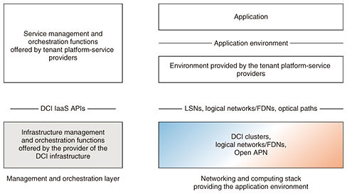
5. DCI infrastructure as a serviceThe DCI infrastructure as a service (DCI IaaS) allows service providers to benefit from LSNs, as described by the DCI architecture, from optical networks as detailed by the Open APN architecture, and Function Dedicated Networks (FDNs)*2 described later, without having to maintain their own infrastructure. The relations between the DCI infrastructure provider, tenant platform-service providers, and end-user applications using such platforms are illustrated in Fig. 4. Tenant platform-service providers may request provisioning of LSNs and networks in-between these LSNs from DCI-infrastructure service providers. Then, tenant platform-service providers deploy middleware or applications on the LSNs and networks. Finally, these resources are offered as a service to end users and their applications. The APIs that tenant platform-service providers use to access DCI IaaS services are then defined. For example, regarding LSNs, which are the main concept of DCI, an API is defined to support actions such as creation, configuration, starting, and stopping.
6. Analysis of the data plane to implement IOWN GF use casesWhen analyzing various use cases, their parts can be classified into data flows and processing components. Therefore, use cases can be expressed as pipelines connecting these elements. One of the first use cases that IOWN GF is targeting is the cyber-physical systems (CPS) area management (AM) use case. A reference implementation model (RIM) as well as a data pipeline describing this use case are detailed in the IOWN GF RIM document published in January 2022 [3]. For example, this use case includes the scenario of first gathering the video streams of groups of 1000 cameras installed in a given area using local aggregation nodes, transferring these large amounts of real-time data to a regional edge cloud, then conducting continuous AI analysis, and finally alerting local security staff of events within the monitored area. The resulting data pipeline is illustrated in Fig. 5.
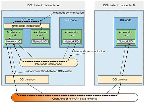
Each dataflow has different requirements toward forwarding. Furthermore, data will need to traverse different data planes. Therefore, the data planes that need to be accelerated need to be identified on the basis of this classification. For example, the intra-node interconnect may be used for communication within a given DCI physical node, and for DCI physical nodes located in different DCI clusters, a data plane using the DCI gateway and Open APN can be used. The DCI FA reference document classifies these data-plane communication patterns, as highlighted in Fig. 6. The data pipeline shown in Fig. 5 is analyzed on the basis of this classification. From this analysis, the DCI FA reference document proposes a data-plane framework for those data-plane patterns that are difficult to support with current technology. The following section gives an outline of this framework.
7. Data forwarding acceleration by remote direct memory accessRemote direct memory access (RDMA) has been proposed as a method of accelerating data-plane long-range data transfers between computing resources that are distributed over a wide area. RDMA was originally developed for communication over relatively short distances up to around 10 meters within datacenters, targeting the communication of high-performance computing applications. However, since the resources of remote datacenters are also used within the overall system in an integrated fashion, RDMA adapted to long-range data transfers becomes necessary. The data-plane framework proposed in the DCI FA reference document uses the widely used RDMA reliable connection (RC) as a transport mode. In this mode, an RDMA framework guarantees the completeness of data to provide a highly reliable connection service. The DCI FA reference document highlights the following points regarding how to avoid performance and reliability degradation when using the RDMA RC between locations separated by long distances. 7.1 Queue-depth optimizationWith RDMA, send and receive operations are controlled by first creating send and receive requests in the form of work queue elements (WQEs). When sending data, a corresponding WQE is placed into a send queue to start the transfer. The amount of messages that can be sent without having to wait for an acknowledgment message from the receiver side can be increased by increasing the maximum length of the send queue of the RDMA network interface card (NIC). Therefore, long-range transmissions can maintain high throughput even when the round-trip time (RTT) is long. The DCI FA reference document gives the following formula to optimize the queue length for long-range RDMA transfers depending on the RTT:
7.2 Increasing the efficiency of data forwarding between RDMA-capable NICs and accelerator cardsTo increase forwarding efficiency, the DCI FA reference document describes the possibility to reduce the number of times that data are copied to minimum by directly exchanging data between RDMA-capable NICs and accelerators and avoiding temporarily storing data in memory buffers as much as possible. 7.3 Reliability when adapting RDMA for long-range communicationBy using a re-send mechanism, the RDMA RC can guarantee the completeness of data transfers even when faced with packet loss. However, especially in the case of long-range communication, re-sending lost data with the RDMA RC requires the RTT to complete, degrading throughput. To avoid such performance issues, the DCI FA reference document suggests that the underlying Open APN network layer should provide a function to provide high-quality optical paths to reduce the number of transmission errors and/or use more efficient re-transmission algorithms to mitigate the impact of errors in long-range transmissions. 7.4 Providing QoS in concert with the DCI control and management planeWithin a DCI cluster, multiple data flows exist. The DCI FA reference document states that classic cloud computing does not allow reserving network resources in advance, and with only the congestion-control algorithms in network appliances and servers, the required QoS cannot often be achieved. Therefore, the DCI FA reference document suggests to let services use resource reservation with different QoS classes. 8. SummaryThe DCI FA reference document outlines the design goals that the computing architecture for the IOWN GF use cases must achieve. The key points are the definitions of the DCI cluster as well as the DCI IaaS service model. Furthermore, CPS AM is analyzed as an exemplary use case, and for transmission between physically separated DCI clusters, a data plane using long-range RDMA is proposed for acceleration. In the future, IOWN GF will proceed with experiments to verify the architectural and technological concepts as highlighted above, and the results as well as remaining issues will then be used to drive further innovation of IOWN GF technologies. References
|
|||||||||||

