|
|||||||||||||||||||||||||
|
|
|||||||||||||||||||||||||
|
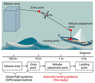
Regular Articles Vol. 22, No. 6, pp. 50–58, June 2024. https://doi.org/10.53829/ntr202406ra1 Millimeter-wave-based Drone Automatic Landing-guidance System for Advanced Maritime OperationsAbstractDrones have gained increased interests from a variety of fields such as logistics and environmental measurements. In the maritime domain, their applications are wide spreading, including cargo transportation, weather observation, fishery exploration, red-tide monitoring, port management, and detection of illegal ships. However, safely navigating drones to ships is challenging due to the swaying caused by waves and the occurrence of poor visibility conditions such as fog and rain. To address this challenge, our team has been investigating a novel automatic landing-guidance system using high-resolution millimeter-wave radar, which is tolerant to weather conditions. With this system, radio frequency identification (RFID)-based wide-range navigation and passive-landing port-based surface-inclination estimation are implemented to consistently guide drones located at a distance to the landing point. Specifically, the system consists of a wide-range flight-guidance method and a surface inclination-estimation method, both of which require a millimeter-wave radar mounted on a drone. The flight-guidance method, called MilliSign, uses corner reflector array-based RFID tags and enables a drone to be guided to a landing point by using the embedded information and position information of the tag. The inclination-estimation method uses a special arrangement pattern of corner reflectors and enables precise inclination of the landing port on a swaying ship for determining the appropriate start time of landing descent. This article investigates the overall system, which consistently guides a drone at a distant point to a landing point for all-weather operation. Keywords: drone, millimeter-wave radar, maritime operation, autonomous landing  1. IntroductionDrones, with their advanced three-dimensional (3D) mobility capabilities, are gaining attention in various fields such as logistics, disaster response, and weather observation [1, 2]. They are expected to serve as an infrastructure for advanced logistics and environmental measurements by applying mobility, sensing, and information-processing technologies in unexplored areas such as the sky, marine areas, and mountainous regions that have been hard to reach. Drones in the maritime domain provide a wide range of use cases, including, but not limited to, cargo transportation, weather observation, fishery exploration, red-tide monitoring, port management, and detection of illegal ships. They play a crucial role in understanding the maritime conditions of Japan, which is surrounded by the sea. To expand the area where drones can operate over a wide range of ocean, it is essential to use the ships as base stations for automatic takeoff and landing. Due to the limited space, human labor, and equipment on a ship, advanced drone flight-guidance technology is necessary to achieve efficient navigation management. However, because the landing surface on the ship moves and sways due to waves, flight control systems based on not only absolute position obtained by the Global Positioning System (GPS) but also relative position are required. Navigation methods using image recognition have been proposed by placing a QR (Quick Response) code as a marker on the landing platform to achieve accurate landing by recognizing the relative positional relationship with the ship [3]. However, the use of image recognition technology becomes difficult and the opportunity to use drones is limited in situations where visibility is poor, such as fog, rain, and nighttime. To overcome this issue, our team has been investigating an automatic landing-guidance system that involves mounting a millimeter-wave radar on a drone that is less affected by weather and reading the radio frequency identification (RFID) tag installed on the ship. By using the RFID tag in the millimeter-wave band for the flight-guidance method, called MilliSign, that we previously developed [4] as a marker for the landing point, it is possible to transmit the embedded information and position to the drone from a position more than 10 m away and guide it accurately. We have also developed a method for estimating the inclination of the landing surface when the positional relationship between the drone and landing point is known using a landing port with multiple reflectors installed on the landing surface [5]. By combining MilliSign and the inclination-estimation method, it is possible to convey the appropriate flight path and landing timing to the rocking surface on which the position and inclination changes over time, enabling safe flight guidance to the ship. However, the working 3D ranges of the tag and inclination-estimation method are different, and to guide a drone located far away to the landing point consistently, it is necessary to appropriately arrange the tags and ports so that the flight path to guide is always within the range of either method. An overview of this system is shown in Fig. 1. We aimed to guide a drone located about 10 m away to the landing point and divide it into three guidance points and two guidance routes. The point where the tag installed near the landing point is first detected with the millimeter-wave radar is set as the entry point. On the basis of the information obtained from the tag, we then guide the drone to the attitude-adjustment point and measure the inclination of the landing surface swaying with the waves there. On the basis of the measured inclination information, we start the landing descent at the appropriate time and finally reach the landing point.
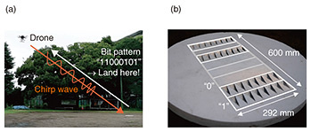
In Section 2, we explain MilliSign using millimeter-wave RFID tags for guiding the drone from the entry point to the attitude-adjustment point and confirm its performance. In Section 3, we explain the method for estimating the inclination at the attitude-adjustment point related to the landing port and confirm its performance. We then discuss the overall automatic landing-guidance system in Section 4, and summarize this article in Section 5. 2. Wide-range flight-guidance method, MilliSign, using RFID tagsIn this section, we describe MilliSign [4] for guiding a drone from the entry point to the attitude-adjustment point, as shown in Fig. 1, and confirm its performance. An overview of MilliSign is shown in Fig. 2.
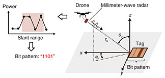
2.1 Readout of bits using slant-range radarA slant-range radar is a radar that emits radio waves diagonally downward from a drone located in the air toward tags, measuring the scattering distribution on the ground. As shown in Fig. 2(b), it can read the arrangement order of reflectors that reflect millimeter waves as a bit string from the airborne radar and measure the position of the entire tag where reflectors are embedded. Therefore, it can read the position and information of tags installed on the ground. A spatially modulated chipless RFID tag [6] is then placed on the ground. The principle of bit string reading by slant-range radar is illustrated in Fig. 3.
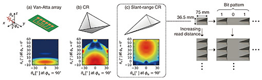
We developed a tag-design method using corner reflectors (CR) to widen the reading range and a signal processing method [6] using the multiple signal classification (MUSIC) algorithm Root-MUSIC for eigenvalue analysis to accurately read the bit string stored in the tag. 2.2 CR-based chipless RFID tag for increasing 3D read rangeWe used a CR structure as an element constituting the developed spatially modulated chipless RFID tag. The CR is composed of three reflector plates connected perpendicularly, and due to the principle of retroreflective reflection, it has a high radar cross-section at a wide range of angles [7, 8]. The Van Atta array structure, which has 2D retroreflective reflection, has often been proposed as a component of chipless RFID tags [9, 10]. However, when considering reading from a reader with 3D positional freedom such as a drone, the CR, which has a wide angular characteristic in both azimuth angle ϕu and elevation angle θu, is suitable as a component of chipless RFID tags. In response to the problem that the maximum θu with retroreflective reflection in conventional CRs is limited to about 20°, as shown in Fig. 4(b), we have achieved an increase in θu (shallower angle) by changing the shape. By arranging this reshaped CR in two dimensions vertically and horizontally, the bit sequence to be stored and the maximum reading distance can also be determined. Figure 4 shows the design method of the developed CR-based chipless RFID tag.
2.3 Accurate readout of bits based on eigenvalue analysisWhen CR tags are densely embedded in the distance direction, the frequency difference that constitutes the received signal changes as the path difference of the scatterers changes. Therefore, the bit-detection accuracy decreases with the fast Fourier transform (FFT), which fixes the frequency basis. Therefore, by using Root-MUSIC [11] for eigenvalue analysis, we can determine the frequency basis that constitutes the received signal and robustly detect bits even for frequency bases that change with the angle. The procedure and principles of Root-MUSIC is as follows. After conducting eigen space analysis of the autocorrelation matrix R of the received signal, we first determine the frequency components that constitute the received signal. Once the size M of R and the maximum number of bases assumed (i.e., the maximum number of scatterers assumed) P are determined, a polynomial Q(z) of order (M – P) can be obtained by eigenvalue decomposition of R as follows:
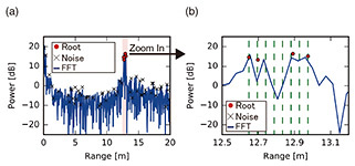
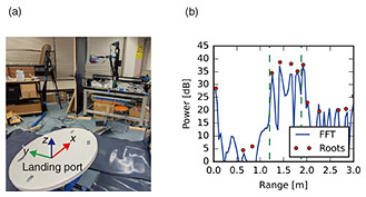
Here, vk is the k-th eigenvector of R, and p(z) is the mode vector, represented as p(z) = [1, z, z2, …, zM – 1]t. The roots zm (1 ≤ m ≤ M – P) are obtained by solving Q(z) = 0, where zm is a complex number and represented as zm = ehmΔt + j2πƒmΔt. Here, zm is the rate of change of amplitude, and ƒm is the frequency. The complex amplitude corresponding to each frequency component can be determined using least squares with s(t). The obtained frequency and complex amplitude can then be converted to distance as 2.4 Experimental resultsWe evaluated the reading performance of the developed CR-type chipless RFID tag and the eigenvalue-analysis method using Root-MUSIC through experiments. In the coordinate system shown in Fig. 3, we present the measurement signal from the millimeter-wave radar when the drone’s position is set at (ru, θu, ϕu) = (12.6 m, 45°, 0°) in Fig. 5. This figure includes the results of both the eigenvalue-analysis method using Root-MUSIC and the conventional method using FFT. Upon examining the enlarged distribution of distance intensity around 13.0 m, where the tag is positioned (Fig. 5(b)), the eigenvalue-analysis method using Root-MUSIC accurately captured the bit sequence “11000101,” demonstrating its ability to precisely estimate the tag’s position and information. It is also evident that the tag’s reflection from the backscattering from the ground can be read with a high signal-to-noise ratio (SNR) of over 15 dB.
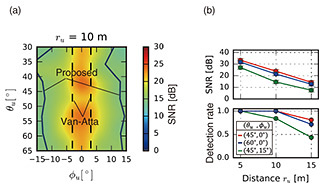
We next evaluated the range within which the tag could be read in the coordinate system shown in Fig. 3. The reading performance was assessed using the detection-success rate and SNR when changing the distance ru, ϕu, and θu. The detection-success rate was calculated by counting the successful reads among the 32 chirps used in a single-radar measurement and expressing the proportion of successful reads as the detection-success rate. The variations in the SNR and reading rate at different positions are shown in Fig. 6. Even at a distance of 10 m from the tag, a reading-success rate of over 90% was achieved within a range of θu greater than 30° and ϕu greater than 20°.
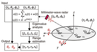
3. Inclination estimation of landing surfaces on shipsIn this section, we explain a prior study [5] on a method for estimating the inclination of the landing surface using the known arrangement of reflectors for the guidance method from the attitude-adjustment point to the landing point shown in Fig. 1, and confirm its performance. This method uses a millimeter-wave radar chip, which is small and lightweight for mounting on drones. While a typical millimeter-wave radar chip achieves a high distance resolution of several centimeters by increasing the chirp bandwidth, the angular resolution is low, at about 10°, due to the limited number of array antenna elements. Therefore, this method is used for embedding multiple reflectors in the landing surface and estimating the inclination from the measured distance between the drone-mounted radar and reflectors. The overview of this method is shown in Fig. 7. In this study, to evaluate the inclination-estimation accuracy using distance-measurement information, one fixed radar and four reflectors were used, and the coordinates of the radar and each reflector were known and expressed.
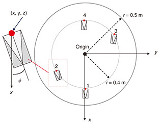
We assumed the following situation: the drone is equipped with a millimeter-wave frequency-modulated continuous wave radar. There are four CRs si {1 ≤ i ≤ 4} at the landing port, and the relative position of the reflectors to the center of the port are known as Pi. The drone can obtain its position from the radar measurement as Pe. If the rotation angle of the port around the x-axis as seen from the fixed coordinates on the ground is θr and the rotation angle around the y-axis is θp, the distance Di(θr, θp) from the drone to the i-th reflector can be calculated as Di(θr, θp) = |Pe – Rx(θr) ・ Ry(θp) ・ Pi| (1 ≤ i ≤ 4), (1) where Rx and Ry are the rotation matrices around the x-axis and y-axis, respectively. By solving four simultaneous equations of Eq. (1), we can obtain rotation angles (θr, θp) and estimate the inclination of the surface. In the experiments, the positions were expressed in a polar coordinate system and the coordinates of the drone were considered the same as the radar coordinates. The radar position Pe was set as (re, θe, ϕe) = (1 m, 45°, 0°). When we denote the position of i-th reflector as (ri, θi, ϕi), then (ri, θi) = (0.4 m, 90°) {1 ≤ i ≤ 4} and (ϕ1, ϕ2, ϕ3, ϕ4) = (0°, 300°, 120°, 180°), which leads to the arrangement pattern shown in Fig. 8. We used a Texas Instruments’ millimeter-wave radar [12] with a carrier frequency of 79 GHz and chirp bandwidth of 4.0 GHz, which provides a range resolution of 37.5 mm. We used the CRs mentioned in Section 2 as the embedded reflectors in the landing port. To obtain accurate distance measurements, the Root-MUSIC-based ranging method was used for processing the raw radar signal [11]. The direction of normal vector of the surface was used as the inclination-estimation-error metric. The measurements were conducted by varying roll and pitch angles as –3 ≤ θr, θp ≤ 3, respectively. The overview of experimental setup is shown in Fig. 9(a).
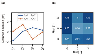
Figure 9(b) shows measurement results of the range-power profile based on Root-MUSIC and range-FFT, which is a standard frequency analysis in radar-signal processing. The graph shows that the obtained roots plotted as red dots provided more accurate distance information than range-FFT. We then rotated the surface and observed the distance deviation caused by the inclination in accordance with Eq. (1). Figure 10(a) shows the distance deviation to each reflector Di {1 ≤ i ≤ N} when measured distances with the flat surface (θr = θp = 0°) were set as standards. The results indicate that radar-ranging measurements could capture the small distance deviation of several centimeters, considering that global navigation satellite system sensors have a root-mean-square error of 12.25 cm for vertical-position estimation. Figure 10(b) shows the inclination-estimation error for each combination of (θr, θp). Since the estimation error is less than 3° and relatively small when θr = 0°, the results indicate that a larger θr deteriorates inclination-estimation accuracy. The reason may be that the close placement of s2 and s3 reduced the inclination-estimation accuracy of θr since distance-estimation errors of D2 and D3 increase the estimation error of θr. Therefore, optimizing reflector allocation will improve inclination-estimation accuracy.
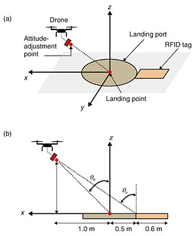
4. Automatic landing-guidance system from detecting landing point to precision landing4.1 Arrangement patternIn this section, we discuss the automatic landing-guidance system that can consistently guide a drone from the approach point through the attitude-adjustment point to the landing point. MilliSign and the inclination-estimation method described in Sections 2 and 3 can be used for information and position transmission and inclination estimation, but the application ranges of these two methods are different. For example, with MilliSign, a reading-success rate of over 90% is achieved for a drone 10 m away within a range of θu over 30° and ϕu over 20°. To apply the inclination-estimation method, however, the drone needs to be located near the point (ru, θu, ϕu) = (1.0 m, 45°, 0°), and the relative position between the drone and landing point must be known. Due to the different application ranges and usable conditions of the two methods, it is necessary to consider an appropriate arrangement method. Figure 11 shows a schematic of the automatic landing-guidance system with the landing port and CR-type chipless RFID tags arranged in parallel.
Figure 11(b) shows the view of Fig. 11(a) on the x-z plane. The angles in Fig. 11(b) are set at θe = 45° and θu = arctan 4.2 ApplicabilityWe discuss the automatic landing-guidance system from the perspective of practicality. In terms of the system’s area, the space on board a ship is generally limited, so a space-saving design is required. The system has side lengths of 1.6 and 1.0 m. In general industrial drones, including the propellers, the drone has a side length of about 1.5 m, so this system does not require more area than the drone occupies. In terms of maintainability, this system does not use any batteries or electronic devices, so there is no need for battery replacement or electrical testing. The system is considered robust and highly maintainable. However, if debris gets into the grooves of the CR, the radio-wave-reflection performance will decrease, so measures are needed to make it less susceptible to dirt. Such measures can be taken, for example, by placing a radome that transmits millimeter waves on top of the tag. 5. ConclusionWe presented an automatic landing-guidance system to guide a drone located at a distance to a landing point on a ship. We introduced MilliSign for enabling position and information transmission using a CR-type chipless RFID tag and our inclination-estimation method for the landing port. We confirmed that it is possible to consistently guide a drone from the approach point through the attitude-adjustment point to the landing point with this system. For future work we will verify the system’s performance through experiments and demonstrate the feasibility of landing on a ship. References
|
|||||||||||||||||||||||||