 |
|||||||||||||||||||||||||||||||||||||||||||
|
|
|||||||||||||||||||||||||||||||||||||||||||
|
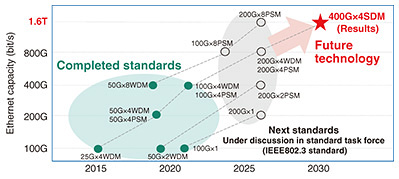
Feature Articles: High-capacity, Low-delay Transmission Technologies Utilizing Optical, Radio, and Acoustic Waves for IOWN/6G Vol. 22, No. 7, pp. 40–47, July 2024. https://doi.org/10.53829/ntr202407fa4 Research and Development of 1.6-Tbit/s-class Ethernet Optical Transmission Technology Supporting Large-scale Datacenter NetworksAbstractTo improve the scalability of large-scale datacenter networks, it is necessary to achieve a 10-km transmission of 1.6-Tbit/s optical signal per fiber, which is more than 4 times the conventional practical level. In this article, we introduce a digital-signal-processing technology developed by NTT that is excellent in resistance to waveform distortion due to transmission systems, an ultra-wideband baseband amplifier integrated circuit module, and optical signal transmission experiment in which 400-Gbit/s optical-intensity-modulation signals were transmitted in 4-parallel spatial division multiplexing using a multi-core fiber cable installed at NTT laboratories. Keywords: optical transmission technology, datacenter network, intensity-modulated direct detection method 1. Large datacenter networks and high-speed EthernetDue to the explosive growth in video streaming services, the expansion of cloud services, and the spread of 5th-generation mobile communication system (5G) services, communication traffic is expected to continue increasing. Therfore, traffic within and between datacenters is expected to increase due to the large number of users accessing datacenters. In datacenter networks, the Ethernet standard is applied as a data-signal transmission method, and the standardization up to 400 Gbit/s was completed as the Institute of Electrical and Electronics Engineers (IEEE) 802.3 standard. Discussions on Ethernet standards of 800 Gbit/s and 1.6 Tbit/s have also started as the next standard [1]. Figure 1 shows the specific configuration of the standardized Ethernet standards (green) and next Ethernet standards (black). Many Ethernet standards use a multi-lane distribution system for parallel transmission to achieve higher Ethernet speeds. For 400-Gbit/s Ethernet signal transmission, for example, four lanes of 100-Gbit/s signals are transmitted in parallel. The method of parallelization is wavelength division multiplexing (WDM)*1 or using parallel single-mode fiber (PSM)*2. The 1.6-Tbit/s Ethernet standard currently under discussion is a configuration in which 200-Gbit/s signals are multiplexed with 8 lanes of PSMs.
As datacenter network traffic increases, Ethernet switches with a huge capacity are installed, and an increase in the number of ports for Ethernet modules is inevitable. Therefore, for future large-scale datacenter networks, an economical 1.6-Tbit/s high-capacity Ethernet module is required to increase the capacity per port and reduce the number of installations. To achieve this, it is necessary to increase the speed to 400 Gbit/s per lane and transmit signals in parallel with one fiber and a small number of lanes (4 lanes). The use of the intensity-modulated direct detection (IM-DD)*3 method, which transmits Ethernet data signals in a simple transceiver configuration, is also an effective means of economizing. Ethernet has standards for transmission distances of 2, 10, and 40 km, but in future large-scale datacenter networks, a transmission distance of 10 km, which broadly supports Ethernet connections within and between datacenters, will be important. The latest Ethernet standard achieves a signal of 100 Gbit/s per lane using the IM-DD method by using the 4-level pulse amplitude modulation (PAM*4-4) method with a symbol rate*5 of approximately 53 GBaud. To speed this up to 400 Gbit/s per lane using the PAM-4 method as before, it is necessary to speed up the signal symbol rate to 200 GBaud or higher. To transmit such ultrafast signals with high quality, it is necessary to increase the bandwidth of the electrical amplifier (driver amplifier for driving optical modulators) in the optical transceiver. With the speedup of the signal, digital-signal-processing technology, which compensates for the distorted signal in the optical transmitter/receiver with extremely high precision at the receiver side, is also necessary, and it is difficult to transmit/receive the signal of 400 Gbit/s per lane with the conventional technology. In such ultrafast signals, the effect of waveform distortion generated in the optical fiber transmission line is very pronounced in proportion to the square of the symbol rate (modulation speed), and the signal quality deteriorates significantly. Therefore, when four different wavelengths are multiplexed in one optical fiber as with the conventional method (WDM method), specification of the wavelength channel far from the zero-dispersion wavelength is essential, and it is difficult to achieve 10-km transmission of the wavelength channel.
2. Development trends in high-speed IM-DD signal transmission and reception technologyFigure 2 summarizes the research results of IM-DD signal transmission in the Ethernet standard wavelength band (O-band) [2–6]. Figure 2(a) shows the results of a demonstration of a transmission rate of 100 Gbit/s or more per lane, and Figure 2(b) shows the results of a transmission experiment with a total capacity of 0.1 Tbit/s or more per fiber. Transmission experiments with relatively high-speed bitrate per lane (up to 400 Gbit/s [3]) are conducted in a single lane due to the large effect of chromatic dispersion*6 [2, 3] (Fig. 2(a)). However, it has been demonstrated that the use of multiple lanes can provide a transmission capacity that exceeds that reported for a single lane, even if the bitrate per lane is relatively low [4, 5] (Fig. 2(b)). For transmission, where the number of lanes to be multiplexed is very large (16 or more), there is concern about the effect of chromatic dispersion even in the O band. Therefore, the space division multiplexing (SDM)*7 method has been combined with the WDM method so that the wavelength range used with the WDM method is not too wide [5].
In an optical transceiver composed of multiple lanes, as described above, an increase in the number of lanes directly leads to an increase in the number of constituent devices and higher prices for the transceiver. Therefore, to develop economical large-capacity Ethernet modules, reducing the number of lanes required by multiplexing high-speed optical signals with low chromatic-dispersion tolerance in multiple lanes is important. In this experiment, we achieved the transmission and reception of IM-DD optical signals exceeding 400 Gbit/s per lane by NTT’s in-house ultra-wideband baseband amplifier integrated circuit (IC) module*8 and ultra-high-precision digital-signal-processing technology (Fig. 2(a)). At the same time, we conducted a 10-km transmission experiment of ultrafast IM-DD signals of 1.6 Tbit/s per fiber with a relatively small number of lanes of 4 (Fig. 1 red and Fig. 2(b)) by implementing chromatic-dispersion management using SDM transmission technology using multi-core fiber [6].
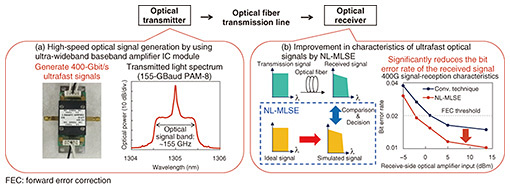
3. NTT proprietary technology details: 400-Gbit/s per-lane ultrafast IM-DD signal transmission/reception technologyAn ultra-wideband baseband amplifier IC module [7, 8] corresponding to frequencies up to 110 GHz based on InP-based heterojunction bipolar transistor (InP HBT)*9 technology, which NTT has been researching and developing, was applied as a driver amplifier for driving optical modulators in the optical transmission system. By newly applying the PAM-8 system, which can reduce the symbol rate by 3/4 that with the conventional PAM-4 system, we were able to generate a stable optical signal with an ultrafast IM-DD signal (155-Gbaud PAM-8) of 400 Gbit/s per lane (Fig. 3(a)). On the receiver side, NTT’s original digital-signal-processing technology uses nonlinear maximum likelihood sequence estimation (NL-MLSE)*10 [6] to emulate distorted signals in optical transmitters and receivers and transmission lines with high accuracy. By comparing the emulated signal with the received signal, the bit error rate of the received signal is greatly reduced, enabling the high-quality reception of the ultrafast PAM-8 signal of 400 Gbit/s per lane (Fig. 3(b)).
4. NTT proprietary technology details: 10-km multi-core-fiber transmission demonstration of 1.6-Tbit/s ultrafast IM-DD signal per fiberThe ultra-wideband baseband amplifier IC module using InP HBT technology and NL-MLSE developed by NTT enabled transmission and reception of ultrafast IM-DD signals at 400 Gbit/s per lane. For this to be a 1.6-Tbit/s signal, a 400-Gbit/s ultrafast IM-DD signal must be transmitted in four parallel channels. In optical fiber transmission lines, signal waveform distortion occurs due to chromatic dispersion, etc., and the effect becomes more pronounced with higher-speed signals. To achieve 4-parallel 10-km transmission using the WDM system used in conventional datacenter networks with an optical fiber, a 400-Gbit/s ultrafast, high-multilevel (155-GBaud PAM-8) signal per lane requires severe dispersion management, i.e., verification of specific chromatic dispersion. The specific dispersion range to be considered can be determined from the wavelength range of the wavelength channel defined in the conventional Ethernet standard, range of the zero-dispersion wavelength of the standard single-mode fiber, and dispersion slope, assuming that the system to be considered follows the conventional Ethernet standard [9]. Since the wavelength channel farthest from the zero-dispersion wavelength is more significantly affected by the chromatic dispersion, the narrower the wavelength spacing of each wavelength channel, the better. The narrowest wavelength spacing among the wavelength channels defined by the conventional Ethernet standard is local area network (LAN)-WDM with a frequency spacing of 800 GHz. The chromatic dispersion to be determined takes into account the LAN-WDM wavelength range (1294.5 to 1310.2 nm). Under the above assumptions, the chromatic dispersions for 2- and 10-km transmissions are −5.7 to 1.9 and −28.1 to 9.3 ps/nm, respectively, as shown in the red area in Fig. 4. Assuming that 200 Gbit/s (106-GBaud PAM-4), which is scheduled for the next Ethernet standardization, can be multiplexed by 4 lanes of WDM for 10-km transmission, the allowable range of chromatic dispersion for 400-Gbit/s (155-GBaud PAM-8) transmission is determined by considering the difference in baud rate and modulation format and is shown in the green area in Fig. 4 (−5.6 to 5.6 ps/nm). These results indicate that, in 2-km transmission, LAN-WDM can transmit 1.6-Tbit/s signals with 4 lanes of 400-Gbit/s per lane (Fig. 4(a)), except for the fiber with the chromatic-dispersion characteristic where the zero-dispersion wavelength is the longest. In 10-km transmission, however, the range of the chromatic-dispersion amount that must be considered is very wide, and the range of the allowable chromatic dispersion amount of 400 Gbit/s is greatly exceeded; thus, parallelization with the WDM method is not practical (Fig. 4(b)). When wavelength channels are evenly spaced near the zero-dispersion wavelength, the narrower the distance between the wavelength channels, the greater the crosstalk between lanes due to nonlinear optical effects.
In this experiment, we solved these problems by adopting an SDM system using multi-core fibers. Specifically, by assigning one wavelength to each core, we set each of the four cores to a wavelength that is less affected by chromatic dispersion, thereby suppressing the occurrence of nonlinear optical effects (Fig. 5). By upgrading the optical signal format from the conventional 4-level (PAM-4) to the 8-level (PAM-8), the symbol rate is reduced by 3/4, and by applying NL-MLSE signal processing, signal-waveform distortion due to chromatic dispersion is greatly reduced.
The transmitters and receivers shown in Fig. 3 were used one by one, and the 400-Gbit/s signal was parallelized by four branches of the optical signal output from the transmitter. Because all the parallelized signals were modulated by the same random symbol sequence, they were connected to fibers of different lengths before they were incident on each core of the multi-core fiber, and the symbol sequence was temporally shifted between each core and each lane, so that inter-lane crosstalk acted as a transmission-performance-degradation factor, as in an actual deployment environment. The multi-core fiber used in this experiment simulates an actual 10-km cable installation environment by laying a 4-core fiber cable in an underground facility of 1-km round trip in an NTT laboratory and fusing it into 10 round trips [10] (Fig. 5). This 4-core fiber uses the same cladding outer diameter*11 (125 μm) as existing fiber, and each core has the same simple step-index-type refractive index structure as existing fiber. Therefore, crosstalk between cores is an issue in the 1.5-μm wavelength band (C-band), which is generally used for long-distance transmission, but the structure is suitable for mass production. The optical characteristics of each core are equivalent to those of the current international standards for optical fibers, and the dispersion of the characteristics of each core is reduced compared with the PSM system using individual fibers. Therefore, the zero-dispersion wavelength of each core is within ±0.33 nm, light-source wavelength of the transmitter can be the same, and light source can be reduced to 1 in 4-parallel configurations (Fig. 6(a)). The crosstalk (amount of light leakage from adjacent cores) between cores during 10-km transmission is about 1/1000 in the 1.3-μm wavelength band (O-band) of the Ethernet standard using the IM-DD system compared with the 1.5-μm wavelength band (C-band), which reduces the optical signal transmission to a level that does not affect it (Fig. 6(b)). Therefore, the configuration of this experiment, which involved a multi-core fiber of standard cladding outer diameter and step-index profile to transmit O-band optical signals in one lane per core, could directly solve the problems of chromatic dispersion, nonlinear optical effects, and crosstalk between cores introduced thus far, and can be achieved economically. Therefore, it is highly compatible with a datacenter network with a very large number of installations.
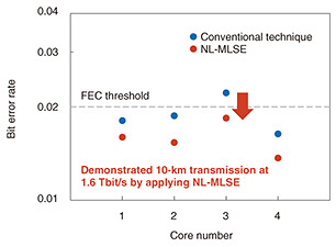
We successfully conducted a field-ambient optical-transmission experiment over 10 km of an ultrafast IM-DD signal exceeding 1.6 Tbit/s per fiber by executing 4-parallel SDM transmission at 400 Gbit/s per lane using a field-installed multi-core fiber and reducing the bit error rate by applying NL-MLSE to the PAM-8 system (Fig. 7).
5. SummaryThe technologies presented in this article are expected to achieve a large capacity, more than 4 times the conventional practical level, and reliably transmit Ethernet signals exceeding 1.6 Tbit/s per fiber, which will be used in future large-scale datacenter networks. Part of this research is supported by the National Institute of Information and Communications Technology, Japan under the commissioned research of No. 20301. References
|
|||||||||||||||||||||||||||||||||||||||||||


