 |
|
|
|
|
|
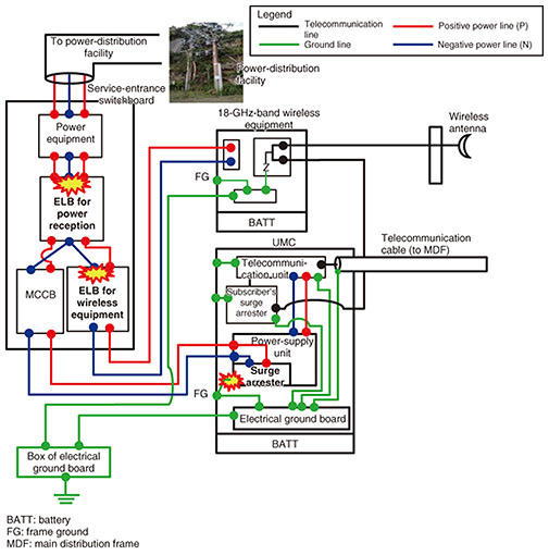
Practical Field Information about Telecommunication Technologies Vol. 22, No. 12, pp. 55–61, Dec. 2024. https://doi.org/10.53829/ntr202412pf1 Case Study of Malfunction in Metallic Subscriber Loop Carrier EquipmentAbstractThis article presents a case study of malfunctions in a piece of metallic subscriber loop carrier equipment due to a switching surge and describes countermeasures against such malfunctions. This is the eighty-fifth article in a series on telecommunication technologies. Keywords: switching surge, earth-leakage circuit breaker, surge arrester 1. IntroductionLarge-scale power outages caused by torrential rain and typhoons have been occurring more frequently in Japan. When a large-scale power outage is resolved and power is restored, there is a risk of an overvoltage due to sudden voltage fluctuations in circuit breakers, transformers, capacitors, and other electrical devices. This overvoltage is called a switching surge because it is generated by the switching operation of these devices. Switching surges can also occur when power is restarted after regular inspections of power-supply equipment in buildings and other facilities. For regular inspections, to prevent telecommunication equipment malfunction caused by switching surges, we can unplug the telecommunication equipment from electrical outlets and turn off the power of the equipment in advance. However, when there are power outages that are not due to regular inspections, we cannot unplug telecommunication equipment from electrical outlets in advance to prevent equipment malfunction caused by switching surges. This malfunction scenario is also true for telecommunication equipment installed outdoors, where the restoration of power after a power outage may cause the equipment to fail. This article presents a case study of malfunctions in a piece of metallic subscriber loop carrier equipment (hereafter, universal modular carrier (UMC)) due to a switching surge and describes countermeasures against such malfunctions. 2. Details of malfunctionAfter a large-scale power outage, customers on a remote island in Japan sometimes claimed that their telephones could not work. Maintenance personnel inspected the situation and found that the earth-leakage circuit breaker (ELB) for 200 VAC (volts alternating current) connected to the power-supply line of the telecommunication system including the UMC (hereafter, ELB for power reception) had been tripped repeatedly. As a result, the backup batteries ran out due to frequent switching from commercial power to battery power supply, leading to the power of the UMC being turned off. This telecommunication malfunction was resolved after replacing the following three components: (i) the ELB for power reception; (ii) ELB for 100 VAC connected to the 18-GHz-band wireless equipment (hereafter, ELB for wireless equipment); and (iii) surge arrester for the power-supply unit of the UMC. The replaced ELB for wireless equipment did not have enough primary-side insulation resistance with respect to ground (0.05 MΩ instead of the required 0.1 MΩ or more at 100 VAC). Since the cause of the frequent tripping of the ELB for power reception was unknown, the Technical Assistance and Support Center (TASC), NTT EAST was asked to provide technical assistance in investigating the cause of the malfunction and propose countermeasures to prevent recurrence. 2.1 Equipment configuration when the malfunction occurredThe configuration of the equipment at the time of malfunction is shown in Fig. 1. A single-phase, three-wire, low-voltage power line is wired into the service-entrance switchboard. An ELB for power reception, a molded case circuit breaker (MCCB) for 100 VAC connected to the UMC, and ELB for wireless equipment are installed in the switchboard, which distributes power to the UMC and 18-GHz-band wireless equipment. Wired with the MCCB, a power-supply unit of the UMC is connected with a surge arrester. The unit converts 100 VAC to 48 VDC (volts direct current) for supplying that power to the telecommunication unit. A box of electrical ground board is installed at the bottom of the same utility pole on which the service-entrance switchboard is installed. In this equipment configuration, the 18-GHz-band wireless equipment had been working even though the UMC was stopped.
2.2 Interior inspection of equipment and on-site investigationFigures 2–6 show the results of the interior inspection of the pieces of equipment (i.e., ELB for power reception, ELB for wireless equipment, and surge arrester for the UMC power-supply unit) that were operated at the time of the malfunction and the installation conditions investigated on site. Results of the inspection are summarized as follows.
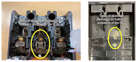
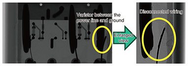
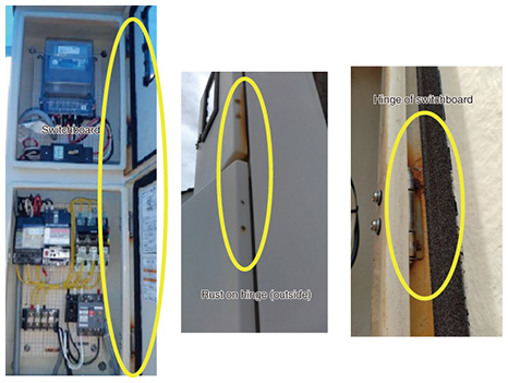
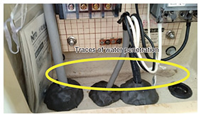
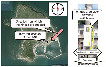
(1) Traces of electrical discharge were observed on the primary contacts and back of the enclosure of the ELB for power reception (Fig. 2). (2) Traces of electrical discharge were observed near the primary contacts and on the back of the enclosure of the ELB for wireless equipment (Fig. 3). (3) Regarding the surge arrester of the UMC power-supply unit, we measured the operating voltage of the varistor with an arrester DC tester (Model 4K1M). The measurement results indicate that the varistor located between the surge arrester and ground was in an open state, i.e., not operating properly. An X-ray inspection system (Shimadzu Xslicer SMX-1020) was then used to look through the internal wiring condition of the surge arrester. The X-ray results indicate that the wiring of the varistor located between the surge arrester and ground was disconnected (Fig. 4). (4) Rust and deterioration of the waterproof seal were observed on hinges of the service-entrance switchboard (Fig. 5). (5) Traces of water penetration were observed at the bottom of the service-entrance switchboard (Fig. 6). (6) To confirm the installation environment of the equipment, we referenced the data of wind direction and speed over the past 10 years at that remote island (Fig. 7). Figure 8 shows the equipment-installation location and wind directions. Since the location is subjected to strong winds from the northeast and northwest, and since the hinges of service-entrance switchboard are on the northeast side, it was presumed they are affected by sea breezes.
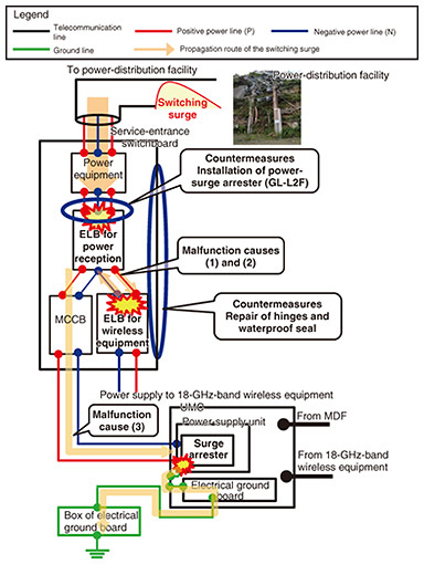
2.3 Presumed cause of malfunctionsFigure 9 shows the propagation route of the switching surge. The presumed causes of the frequent malfunction of the ELBs are as follows.
(1) During a large-scale power outage (September 2022), the first malfunction occurred. It was presumed that the switching surge at the time of power restoration passed through the power equipment and flowed into the ELBs for power reception and for wireless equipment. Therefore, a large current flowed between positive and negative power lines in the ELB for wireless equipment, which tripped the ELB for power reception (malfunction cause (1) shown in Fig. 9). It was also presumed that at that time, electrical discharges occurred on the primary contacts of the ELB for power reception and inside the ELB for wireless equipment. (2) Frequent malfunctions of the ELB for power reception occurred after the first malfunction. The insulation resistance between the primary lines of the ELB for wireless equipment was reduced by half from the required 0.1 to 0.05 MΩ. It was thus assumed that the ELB for wireless equipment was prone to current leakage from positive power line to negative power line, and the ELB for power reception was prone to being tripped by the leakage current. The decrease in insulation resistance may also be partly due to water intruding into the service-entrance switchboard, as indicated by traces of water penetration in the switchboard (malfunction cause (2) shown in Fig. 9). (3) It is unknown when the wiring of the varistor between the power line and ground for the UMC surge arrester became disconnected; however, it was estimated that the switching surge during the first malfunction was also a cause of the subsequent malfunctions (malfunction cause (3) shown in Fig. 9). (4) The deterioration of the hinges of the service-entrance switchboard and water penetration to the switchboard are assumed to have occurred for two reasons: (i) the hinges and seals on the right side (northeast side) were more sensitive to deterioration due to sea breezes from the northeast than other areas of the switchboard and (ii) strong winds and rain from the northeast created an environment in which moisture can easily enter the switchboard. 2.4 Proposed countermeasuresWe proposed countermeasures to prevent malfunction of the ELBs in the event of a switching surge occurring when power is restored after a power outage or in the event of a lightning surge flowing in from the power line (Fig. 9). The countermeasures are (i) installing a power-surge arrester (GL-L2F) on the primary side of the ELB for power reception and (ii) repairing the deteriorated hinges and waterproof seals of the service-entrance switchboard to prevent moisture intrusion into the switchboard. 3. ConclusionWe investigated the malfunction of a UMC due to a switching surge and proposed countermeasures to prevent recurrence of the malfunction. TASC will continue contributing to solving on-site problems through technical support for those involved in the maintenance and operation of telecommunication facilities. |

