|
|
|
|
|
|
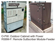
Practical Field Information about Telecommunication Technologies Vol. 12, No. 4, pp. 62–66, Apr. 2014. https://doi.org/10.53829/ntr201404pf1 Case Studies of Insulation Failures in Outdoor Facilities and Countermeasures against FailuresAbstractIn this article, we introduce failure cases in outdoor access equipment and a countermeasure to them. This is the twenty-second in a bimonthly series on the theme of practical field information on telecommunication technologies. This month’s contribution is from the Materials Engineering Group, Technical Assistance and Support Center, Maintenance and Service Operations Department, Network Business Headquarters, NTT EAST. Keywords: countermeasures, access equipment, outdoor facilities  1. IntroductionNTT EAST has been developing and deploying outdoor optical access equipment that accommodates multiple lines (referred to below as remote terminal (RT) equipment) in order to economically upgrade the metallic cable network. Compact RT equipment can be installed in small spaces such as in the corners of public sites and facilities and under pedestrian bridges, and many units have been installed throughout Japan (Fig. 1).
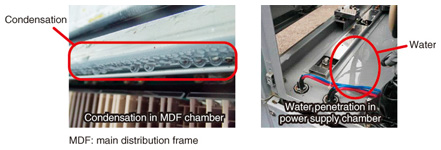
However, more than ten years have passed since the development and deployment of this equipment began, and in recent years, the number of requests for consultation regarding problems in compact RT equipment has increased. At the Technical Assistance and Support Center, we have analyzed the cause of insulation failures throughout the country that have been brought to our attention in these consultations and have studied countermeasures to prevent such failures. We report here on our investigation into the cause of insulation failures in compact RT equipment and also describe a preventive measure. 2. Insulation failures in compact RT equipmentCompact RT equipment has been designed for outdoor installation and the need to maintain communication functions even when the equipment is exposed to wind and rain. However, equipment that has been in the field for more than ten years is inevitably affected by the installation environment (rain, humidity, corrosive gases, etc.) over the long term. Such equipment is at greater risk for problems as deterioration progresses. Consultations on insulation failures in compact RT equipment have been requested from all regions of Japan from Okinawa to Hokkaido. These failures, moreover, have been reported in all seasons, from Japan’s relatively long rainy season and severe typhoon season to its dry winter season. Similar characteristics have been found in compact RT equipment in which insulation failures have occurred. Condensation has been observed inside the equipment on the inner side of the door and on the underside of the top panel, and traces of water have been found on the inspection sheet inside the equipment. In the worst cases, water has been found to collect on the floor of the power supply chamber (Fig. 2). These conditions led us to infer that external environmental factors such as rain and humidity contributed to the insulation failures in the equipment.
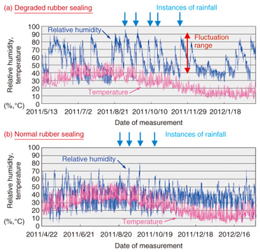
The Technical Assistance and Support Center conducted a survey on the causes of individual failures in order to develop countermeasures against them. 3. Causes of severe condensation inside equipmentHumidity inside compact RT equipment tends to rise whenever the equipment doors are opened and closed in rainy weather when deploying new circuits or carrying out maintenance. Most equipment, however, does not develop problems when exposed to such conditions, which led us to believe that equipment in which insulation failures occur are subjected to particular conditions. The changes in temperature and humidity inside equipment were measured when there were cases of normal and degraded rubber sealing. The results are shown in Fig. 3. These graphs show that after a rainfall, the internal relative humidity rises remarkably in equipment with degraded rubber sealing, whereas it shows little change in equipment with normal rubber sealing. In other words, it can be inferred that the housing is not airtight in equipment with degraded rubber sealing, and that the equipment can consequently be affected by moisture in the outside air or can be penetrated by rainwater.
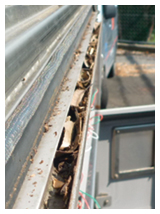
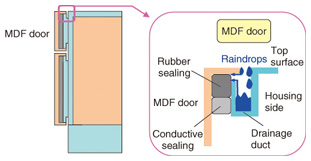
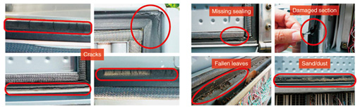
A drainage duct is installed in each door of the compact RT equipment in order to lower the risk of rainwater penetration. However, if fallen leaves clog the drainage duct (Fig. 4), or if the amount of water flowing into the drainage duct is excessive due to heavy rain, the rubber sealing may come into contact with rainwater as the drainage duct overflows. This raises the risk of rainwater penetrating the equipment through gaps in the rubber sealing (Fig. 5). Surveys that we have conducted to date have revealed that rubber sealing often deteriorates and cracks when equipment doors are frequently opened and closed during circuit-deployment or maintenance work. They have also shown that it is not unusual for rainwater to penetrate the equipment when leaves and branches become wedged between the door and the housing when the door is opened and closed (Fig. 6).
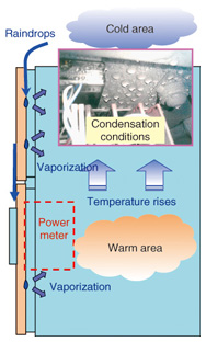
4. Mechanism behind insulation failureThe interior of compact RT equipment is always in a warm state due to heat generated by the power supply section and other areas. At night, the outside surface of the housing can be cooled by cold outside air, and if the warm air inside the equipment comes into contact with the cooled inner side of the housing under such conditions, condensation can occur due to the temperature difference. However, the occurrence of condensation does not necessarily mean that an insulation failure will occur. We examined problem equipment in various regions and found that insulation failures had occurred under severe condensation in which many water droplets formed on the inside of the top panel. With this in mind, we postulated that insulation failures occur by the following mechanism (Fig. 7).
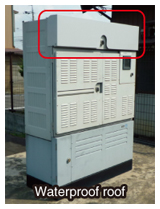
(1) Rainwater and humidity (moisture) penetrate the equipment through gaps between the rubber sealing and housing. (2) Temperature inside the equipment rises when the penetrated rainwater vaporizes due to heat inside the equipment. (3) The temperature difference between the inside and outside of the equipment causes condensation (water droplets) to form on interior parts of the equipment at relatively lower temperatures (such as the top panel). (4) The water droplets drop into the gaps between terminals of the equipment, causing an insulation failure to occur. 5. Overview of preventive measureHere, we introduce a preventive measure for the RSBM-F (remote subscriber model-feeder) model of compact RT equipment. In the past, the response taken when insulation failures occurred was to ask the equipment manufacturer to replace the rubber sealing. This approach, however, was costly and time consuming and did not guarantee that an insulation failure would not occur again. Given these problems, the Technical Assistance and Support Center proposed a countermeasure commonly referred to as a waterproof roof to prevent water penetration (Fig. 8) instead of replacing the rubber sealing. The idea behind this waterproof roof was to prevent the penetration of rainwater that can trigger an insulation failure. In addition, we collaborated with the manufacturer to (1) give the roof a structure tailored to the part of the equipment that was most susceptible to water penetration, thereby lowering costs, and to (2) optimize the structure for more efficient maintenance operations.
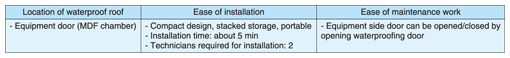
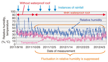
The features of the developed waterproof roof are listed in Table 1, and the half-year result of a test case using the roof on actual equipment throughout Japan is shown in Fig. 9. This graph indicates the relative humidity before and after installation of the waterproof roof. It is clear from these results that installing the waterproof roof suppresses the fluctuation in relative humidity when rainfall occurs. Consequently, installation of a waterproof roof has the effect of preventing the penetration of rainwater and suppressing a rise in humidity within the equipment, which means that this countermeasure is effective in preventing insulation failures.
6. ConclusionIn this article, we introduced case studies of insulation failures in compact RT equipment and a preventive measure. Our findings can be summarized as follows. - Insulation failures frequently occur in equipment within which rainwater has penetrated through rubber sealing. Attention should be paid not only to cracks in the sealing and sealing that is missing due to aging but also to cases in which fallen leaves and sand and dust become wedged between the sealing and housing when the equipment door is opened and closed. - Preventing the penetration of rainwater through the rubber sealing can suppress a rise in humidity within the equipment; therefore, installing a waterproof roof can be expected to prevent the occurrence of insulation failures. Looking forward, we consider the possibility that the number of insulation failures in compact RT equipment will increase as equipment continues to age. To prevent failures from happening in the first place or to at least reduce the occurrence of failures, it is essential that equipment be adequately maintained as a preventive measure. The Technical Assistance and Support Center works continuously to improve the reliability of all NTT facilities. We ask those having a difficult time with equipment-related problems and countermeasures to feel free to contact us. |