 |
|
|
|
|
|
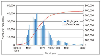
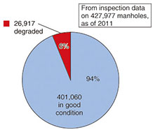
Feature Articles: R&D on Maintenance and Management Technologies for Telecommunication Infrastructure Vol. 12, No. 10, pp. 31–37, Oct. 2014. https://doi.org/10.53829/ntr201410fa5 Repair and Reinforcement Technology for Safe and Secure Concrete Structures that Have a Long Service LifeAbstractA vast number of concrete manhole and tunnel structures managed by NTT are 30–40 years old, and there is obvious degradation in some of those facilities. To address this problem, the NTT Access Network Service Systems Laboratories has been conducting research and development on the technology needed to extend facility use long into the future, including technology for more efficient and cost-effective maintenance and management, accurate measurement of the durability of existing facilities, and effective and economical repair and reinforcement. This article describes the direction and future development of that work. Keywords: concrete structures, durability evaluation, repair and reinforcement 1. Research and development (R&D) on manhole maintenance and management1.1 Current state of maintenance and managementNTT has about 680,000 manholes throughout Japan (Fig. 1). They serve as connection points for telecommunication cables and hubs for customer lead-in cables, and they also provide space for maintenance work. The majority of manhole facilities were constructed from 30 to 40 years ago or earlier, and degradation such as concrete cracking, concrete separation, and rebar exposure has become evident in recent years. Currently, only 6% of all manhole facilities have been determined to be degraded (Fig. 2); however, a significant number of this group are affected by rebar corrosion and require repair or reinforcement (Fig. 3). The cost of repairs is expected to increase as these facilities continue to age.
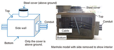
Because manholes are buried at relatively shallow depths of from several tens of centimeters to several meters below the surface of roads, they are susceptible to effects from the weight of vehicles (live load). There was a large increase in live load with the expansion of goods distribution that followed the period of high economic growth when many of the manholes were constructed. As a result, even though the facilities were designed to have sufficient strength, some were subjected to loads beyond what was assumed at the time of construction. Accordingly, a method is needed to evaluate durability that appropriately takes into account future aging of facilities and environmental factors such as changes in the live load. Additionally, technology for economical repair and reinforcement that matches the evaluated durability is necessary. 1.2 R&D directionThe two basic types of manhole structures are steel reinforced concrete (about 580,000 in service) and resin block concrete (about 100,000 in service). Resin block concrete manholes are constructed with high-strength resin concrete, and inspection results show there is relatively little degradation of this type. Therefore, in our continuing investigation, we are targeting steel reinforced concrete manholes that have obvious rebar corrosion. A schematic and a photo of a steel reinforced concrete manhole are shown in Fig. 4.
The degradation in steel reinforced concrete manholes indicates that rebar exposure that progresses from cracks occurs mainly on the ceiling and is therefore considered to be an effect of the live load on the facility. Furthermore, the resistance to the live load on the top of the manhole structure is maintained primarily by the rebar, so manhole safety and security requires particular attention to rebar corrosion in the ceiling of the structure. Manholes can be broadly grouped into the earliest reinforced manholes, which conform to the standards of 1956 and were constructed in a period when traffic was relatively light, (about 430,000 in service), and those that conform to the more stringent 1977 standard (about 250,000 in service). Inspections reveal that manholes in the first group account for a relatively large proportion of the degraded facilities, so we must place priority on that group. Currently, there are two ranks for degradation, but the degree of degradation actually varies from facility to facility. The method of repair and reinforcement also varies according to the degree of degradation. Thus, a more detailed degradation ranking system is needed to lower the repair cost. Nevertheless, the availability of skilled technicians is expected to continue to decrease into the future, and consequently, appropriate evaluation of the degree of degradation by inspectors, and determination of the optimum repair and reinforcement method are likely to become increasingly difficult. Therefore, the NTT Access Network Service Systems Laboratories has been developing a simple method that can be applied on-site for evaluation of degradation in the top part of the 1956-standard manholes and a method for setting repair and reinforcement criteria based on the degree of degradation. 1.3 Evaluation methods for manhole maintenance(1) Evaluation of durability by the degree of degradation On the basis of the assumption that the strength of the rebar governs the durability of the manhole, we conducted bending strength tests on a beam model of part of the ceiling of a manhole to determine the relation of rebar corrosion to manhole durability. The results showed that the relation of the amount of rebar corrosion to the decrease in durability in ordinary reinforced concrete structures can also be applied to NTT manholes. As a simple on-site method of evaluating the durability of manholes, which vary in size and depth below ground level, we have also been investigating structural calculations using the known formula regarding the relation of the amount of rebar corrosion to the decrease in durability for ordinary reinforced concrete structures. This approach holds promise as a means of setting the criteria for determining when repair or reinforcement is necessary. (2) Approach for making appropriate structural calculations for 1956-standard manholes Road traffic was much lighter when the 1956-standard manholes were built than it is today, so the load on the manholes was considered to be concentrated. Later, however, the amount of traffic increased, and the load on the manholes became more constant and evenly distributed. It thus became necessary to evaluate durability under a distributed load. A search of the literature for a correction formula for structural calculations that applies the current equally distributed load condition produced a way to do structural calculations for 1956-standard manholes under equally distributed loads. An evaluation of the validity of this approach by a manhole maintenance study group in 2013 showed good prospects for applicability. Currently, we are developing a simple calculation formula that we plan to test in the laboratory with the objective of establishing a simple, on-site evaluation method. 1.4 Future developmentAlthough degradation has been confirmed in only a small percentage of manholes, it will continue, and increased degradation is a concern. Because the manholes are buried beneath roads, renovation is not a simple matter, and we must rely on enhanced maintenance and management to extend the service lifetime. Furthermore, maximum efficiency is necessary in determining the present condition of the facilities and dealing with any problems discovered. This is because the approximately 680,000 facilities are scattered across the country, the cost cannot simply be assigned per facility, and the work force is aging. We are currently working on a simple method of evaluating durability based on the degree of degradation without using structural calculations. Future R&D will be aimed at developing reinforcement methods that renovate the degraded concrete and that have long-term effectiveness to extend the service life of the entire manhole facility and achieve higher efficiency in maintenance and management. 2. R&D on tunnel maintenance2.1 Current state and issuesThe deterioration of aging infrastructure facilities is becoming a problem that affects our whole society. Forty years or more have passed since the peak period of NTT telecommunication tunnel construction, and concerns for the future are growing as concrete degradation increases due to the intrusion of underground water and its corrosive effect on rebar. Tunnels house the large numbers of cable that lead out from telecommunication buildings. In an analogy with the human body, they would correspond to the aorta of the heart. Any problem that arises with the tunnels can affect the entire telecommunication network, so it is crucial to keep these important facilities in good working order (Fig. 5).
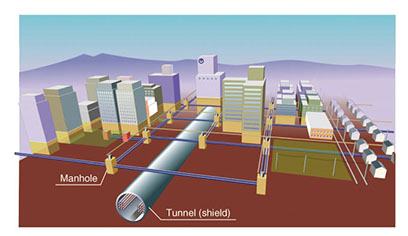
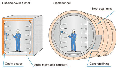
There are two types of tunnels: cut-and-cover tunnels and shield tunnels. Cut-and-cover tunnels are constructed of steel reinforced concrete and have a rectangular cross section. They are built by excavating to a relatively shallow depth of from 5 to 10 m below the ground surface. Shield tunnels have a circular cross-section and are constructed by boring through the earth at depths from 15 to 30 m underground using a shield tunneling machine (Fig. 6).
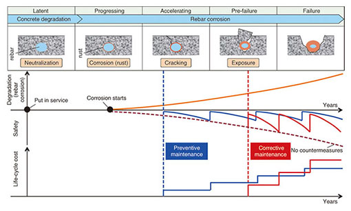
Tunnels range from several tens of meters to several hundreds of meters in length. There are about 650 km of telecommunication tunnels in Japan in total, mainly in urban areas, and renovation of these facilities is very difficult. Accordingly, maintaining safety over a long service life and curtailing maintenance costs are major issues in maintenance and management. Cut-and-cover tunnels were constructed in an earlier period than shield tunnels, and degradation such as rebar corrosion and concrete separation has been observed in some of them. Therefore, we have carried out planned maintenance work for the cut-and-cover tunnels by setting priorities. Specifically, we optimize the scope and timing of repair work according to a life cycle cost evaluation based on degradation criteria and prediction of degradation in steel reinforced concrete. That work is founded on an accurate understanding of facility degradation states obtained using management tools and a periodic inspection database of inspection results (Fig. 7).
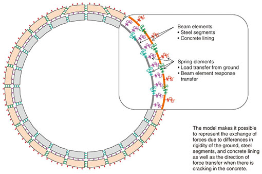
2.2 Direction of R&DThere are several different types of ordinary shield tunnel structures, but most consist of steel segments and a concrete lining. Other tunnels that have similar structures include some sewage tunnels, although they differ in the materials used and other details, so the structures are not strictly the same. Therefore, R&D concerning evaluation of facility durability and repair and reinforcement must be done independently. NTT telecommunication shield tunnels also have the same basic structure, but they differ in their dimensions and installation environment. Also, the actual constructions of those tunnels were based on individual designs. We have been devising required maintenance measures according to individual designs while managing individual states according to inspection results. Our R&D target, however, is to create a highly general standard method that is based on the basic structure and that can accommodate individual environmental conditions. To deal with the reduced availability of technicians in the future due to the aging work force, we are developing maintenance techniques that can be performed simply and easily by workers who do not require advanced design skills in order to allow the continued safe use of facilities with long inspection intervals and without the need for repeated maintenance. 2.3 Evaluation method for shield tunnel maintenance and managementShield tunnels are designed to resist loads acting on the structure, for example, soil pressure, by the steel segment alone. The concrete lining is intended to prevent corrosion and seepage of underground water into the tunnel. Conventionally, the durability of completed shield tunnels is evaluated by applying the same design calculation method as that used at the time of construction. However, it became clear in experiments conducted with cross-section models of actual tunnels that the concrete lining also plays a role in durability. That is to say, use of the design calculation method for tunnel construction to evaluate existing shield tunnels may underestimate their durability. Therefore, taking the concrete lining into account in the durability evaluation makes it possible to avoid excessive reinforcement and to maintain safety economically when considering the necessary reinforcement in the event of degradation due to corrosion of steel segments. We have completed the development of this new evaluation method. The new evaluation method for existing tunnels uses a beam-spring computational model that is used for the cross-sectional influence analysis. We devised an analytical model that can reproduce the responses of steel segments and the concrete lining. That analytical model can also represent the response transfer due to cracks or non-uniformity in the concrete lining (Fig. 8).
2.4 Future developmentAn important future maintenance goal is to reduce the number of facilities that require maintenance. One of our current tasks is to develop a repair method that effectively extends the service life by making it possible to prevent water from coming into shield tunnels over the long term. Water seepage is one of the factors that necessitate frequent repairs. We are also working on a method of reinforcing the strength of degraded parts using a simple and minimum structure. We intend to continue working on capabilities that are necessary for optimum timing in planned maintenance, including increasing the efficiency of inspection work, applying automation, and improving the accuracy of methods for predicting the progression of corrosion and other forms of degradation. In the future, we will continue to seek an overall picture of an effective tunnel maintenance cycle and to develop the optimum solution for operations. |

