|
|||||||||||||||||||||||||||||
|
|
|||||||||||||||||||||||||||||
|
Regular Articles Vol. 19, No. 3, pp. 53–62, Mar. 2021. https://doi.org/10.53829/ntr202103ra1 Increasing Capacity of a Strictly Non-blocking Clos Network Composed of Optical SwitchesAbstractClos networks are widely used due to their non-blocking property. However, in strictly non-blocking Clos networks composed of ordinary optical switches (switches with equal numbers of input/output ports), we find that a substantial number of ports can remain unused, which decreases their efficiency. This inefficiency comes from the implicit restriction that the two sides of switches have distinct roles, i.e., ports on one side are connected to endpoints (terminals) while those on the other side are linked to switches. Removing this restriction provides greater freedom in constructing a network and can increase capacity without losing the strictly non-blocking property. We propose a new strictly non-blocking network and provide several theorems that address network capacity. Numerical experiments show that the proposed network has up to 30% more capacity compared with a strictly non-blocking Clos network. Keywords: non-blocking switching networks, Clos network, network design  1. IntroductionConstructing non-blocking switching networks [1], where connections can be established between any pair of idle ports, remains a vital issue in the field of network design. Such networks have been applied in many areas such as telephone networks [2], asynchronous transfer mode networks [3], optical switching with wavelength-division multiplexing technologies [4], and time-division packet switching [5]. A rich body of literature has been produced on non-blocking networks with the goal of constructing larger-capacity networks [6, 7]. Clos networks [2] are classic networks, and their capacity has been extensively analyzed [8], e.g., 10,000 connections can be accommodated using 59 2000-port switches arranged in a three-stage network. To the best of our knowledge, studies on non-blocking networks made the implicit restriction that switches have two facing sides with several ports, and only one side can be used to connect to endpoints [9, 10]. For example, in Fig. 2, for switches in the input layer, the left side is connected to endpoints (t’s) while the right side is linked to switches. This restriction makes it easy to understand the network, but it might decrease the efficiency of a Clos network if it consists of ordinary square switches (switches with equal numbers of input/output ports) [11, 12]. As discussed in Section 3, a substantial number of ports has to remain unused in a Clos network, e.g., in Fig. 2, if unused (black) ports are connected, the capacity would not increase or the network would lose its non-blocking property. We focus on a non-blocking switching network with greater capacity than the Clos equivalents. To increase capacity, we remove the above implicit restriction while still using square switches, which have equal numbers of input/output ports, as used in previous studies [9, 10]. To the best of our knowledge, this is the first study on maximizing the capacity of non-blocking networks that use square switches without the above restriction. Among the several known non-blocking properties [1], we investigated non-blocking networks in the strict sense (any idle port can be connected independent of current connections) with the most fundamental form of space-division multiplexing*1. Note that we focus on networks with only a single intermediate layer to mitigate signal attenuation. Since our focus is on the strict non-blocking property, routing issues are not discussed. The contributions of this article are summarized as follows.
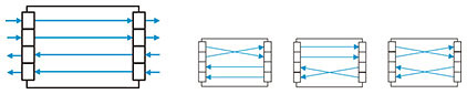
2. Preliminaries2.1 Problem statementThe basic switching component is represented as a square switch, as illustrated in Fig. 1. A square switch has two sides, and each side has N ports. Although input and output ports can coexist on the same side, we are only allowed to connect an input port on one side with an output port on the other side. We assume that all switches have equal N. The size of a square switch is defined as N.
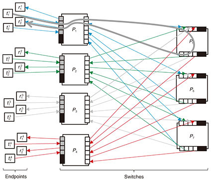
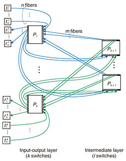
A switching network is defined as a set of switches connected by directional links (optical fibers), and the network is connected to endpoints, as illustrated in Fig. 2. Ports connected to an endpoint are called external ports, while the other ports are called internal ports. Ports without links are called unused ports. Since links have a direction, all external/internal ports and endpoints are classified as either transmitting or receiving. Every transmitting port/endpoint is allowed to connect only with a receiving one. We consider switching networks with a single layer of intermediate switches (intermediate switches are those without external ports) such as one-sided two-stage (Fig. 2 and Fig. 3) and two-sided three-stage (Fig. 4) networks.
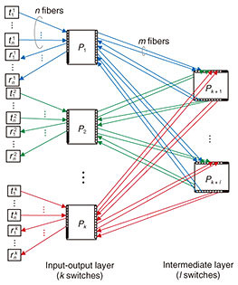
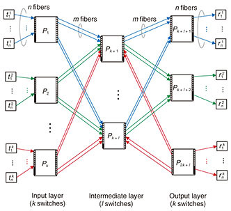
Connection requests are classified into two categories: creation and termination. A creation request, specified by a pair of idle endpoints, triggers the establishment of a path between the endpoints. In Fig. 2, two endpoints Strictly non-blocking networks are designed to accept any request sequence without requiring the rearrangement of existing paths. Moreover, paths used to satisfy creation requests should be chosen arbitrarily. Thus, the path-selection algorithm is outside the scope of this article. Our problem, the connection maximization problem, is defined as follows. Given the number of switches, construct a strictly non-blocking network that has the maximum number of connections. This maximum number of connections is the capacity of the network. In Fig. 2, given seven switches, eight connections can be established between the eight transmitting endpoints and eight receiving endpoints. 2.2 Current approach: Clos networksThis subsection reviews current non-blocking networks, i.e., their connection schemes, non-blocking conditions, and formulations of the connection maximization problem. We explain two current Clos networks: unfolded Clos [2, 6, 9] and folded Clos [7, 10]. Note that an unfolded Clos network is usually called just a Clos network, but to eliminate the ambiguity between folded and unfolded, we explicitly call it an unfolded Clos network. The disadvantages of these networks are analyzed in Section 3. These networks are similar, but they have different capacities, as discussed in Section 5. As explained in the Introduction, these networks have an implicit restriction; ports on one side are either all external or all internal; mixing is not permitted. 2.2.1 Folded Clos networksFigure 3 illustrates a folded Clos network [7, 10]. A folded Clos network has k > 2 switches in the input-output layer and l switches in the intermediate layer. The case of k ≤ 2 is ignored because it can support at most N connections, and a single switch is sufficient. The right side of each switch in the input-output layer is connected to each side of the switches in the intermediate layer with m fibers. The left side of each switch, Pi, in the input-output layer is connected to n transmitting endpoints, { The network is strictly non-blocking if and only if [7] Therefore, as illustrated in Fig. 2, if we increase the number of external ports, n, to 3 from 2, i.e., 3 transmitting external ports and 3 receiving ones, then the network loses its strictly non-blocking property. In folded Clos networks that use at most a switches with N ports, the maximum number of connections, i.e., the capacity 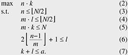 2.2.2 Unfolded Clos networksFigure 4 illustrates an unfolded Clos network [2, 6, 9]. Its connection scheme is similar to that of folded Clos networks. We consider only k > 1 for the same reason given for folded Clos networks. This network is strictly non-blocking if and only if [6] As with a folded Clos network, the maximum number of connections, i.e., the capacity 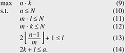 3. Disadvantages of using Clos networksThis section explains the disadvantages of Clos networks. Moderately sized strictly non-blocking folded Clos and unfolded Clos networks must have relatively large numbers of unused ports. The above propositions show that the capacity of folded Clos or unfolded Clos networks increases and more ports are unused: the number approaches 4. Proposed networkIn this section, we explain the proposed network that is based on folded Clos networks. First, we explain the proposed network and its non-blocking condition. We then compare its capacity with that of Clos networks from the theoretical viewpoint. 4.1 Proposed network and its non-blocking conditionFigure 5 illustrates the proposed network. Both sides of the input-output layer are connected to endpoints. At the left side of each switch in the input-output layer, n ports are connected to receiving endpoints, while every m port is connected to the down side of a switch in the intermediate layer. The right side mirrors this configuration. The proposed network offers n · k connections in total. We consider only k > 2 as per a folded Clos network. We confirmed that the construction of the proposed network is feasible on commercially available optical switches.
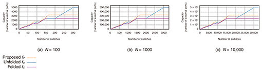
The strictly non-blocking condition, Condition (1), does not change, and the proof is almost the same as for a Clos network [2, 6] (the proof is given at the end of this subsection). The maximum number of connections, i.e., the capacity 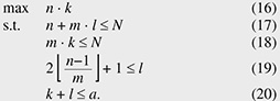 As discussed in Section 5, the proposed network has less unused ports compared with current networks because the proposed network does not have the implicit restriction, that is, a single side in the proposed network can have both external and internal ports. Finally, we give a proof of Proposition 3. Next, we discuss necessity. Suppose l is 2 4.2 Capacity comparisonThis subsection compares capacity from a theoretical viewpoint. We show that the proposed network has equal or larger capacity than a folded Clos network (Theorem 1). With regard to an unfolded Clos network, we give only a sufficient condition for the proposed network to have equal or larger capacity (Theorem 2). Due to the complexity of the discrete nature of integers, it is intractable to analyze the remaining case, i.e., the case that Theorem 2 does not cover. To compare the remaining case, we conducted a numerical evaluation, as discussed in Section 5. First, we prove that the capacity of the proposed network Proof. Suppose that the connection parameters (k, l, m, n) are feasible for a folded Clos network. That is, (k, l, m, n) satisfy Constraints (3), (4), (5), (6), and (7). Then, it is sufficient to show that (k, l, m, n) are also feasible for the proposed network. The only difference between the proposed and folded Clos networks is that a folded Clos network has Constraints (3) and (4), whereas the proposed network has Constraint (17). We have Next, we give a sufficient condition for the proposed network to have equal or larger capacity to an unfolded Clos network. To prove Theorem 2, we use the following proposition and lemma. First, we give a proof of the lemma, then provide a proof of the proposition, and finally prove Theorem 2. 5. Numerical evaluationThis section numerically compares the proposed network with folded and unfolded Clos networks*2. We now show that the proposed network has improved capacity. First, we show that switch size slightly affects the results. Figure 6 shows the capacity (y-axis) and number of switches used (x-axis). We plot the results for the folded Clos, unfolded Clos, and proposed networks, that is,
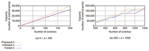
Next, we compared the capacity of the proposed network with folded Clos and unfolded Clos networks. We investigated plots for a certain switch size since, as we saw above, the switch size slightly affects the plots. We chose N of 1000. Figure 7 is an enlargement of Fig. 6(b), i.e., replots the curves with smaller ranges of a, since it is difficult to tell the difference among the three lines from Fig. 6(b) when a is relatively small. Figures 7(a) and 7(b) illustrate the plots for 0 ≤ a ≤ 200 and for 200 ≤ a ≤ 1200, respectively. These three figures show that the proposed network has equal or larger capacity than the folded Clos network and that the proposed network has equal or larger capacity than the unfolded Clos network if a ≤ 2.3N. In fact, the proposed network has up to about 30% more capacity. For example, when the number of available switches a is 833, the capacity of a folded Clos network is 125,000 with (k, l, m, n) = (500, 249, 2, 250), and that of an unfolded Clos network is 125,250 with (k, l, m, n) = (250, 333, 3, 501), whereas that of the proposed network is 167,000 with (k, l, m, n) = (500, 333, 2, 334). We also compared capacity using other switch sizes, N ∈ {200, 300, ..., 900}
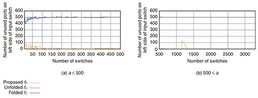
Finally, we compared the number of unused ports on the left side of the input switch; those of a folded Clos, unfolded Clos, proposed networks are N−2n, N−n, N−n−ml, respectively. Figure 8 shows the number of unused ports when N = 1000. In the folded Clos and unfolded Clos networks, almost half the ports remained unused, whereas, in the proposed network, the number of unused ports was less than 10 in more than 90% of a ≤ 3000. The largest number of unused ports was 134 when a = 1155. At this point (a = 1155), m of the optimal connection parameters decreased to 1 from 2, and this change made some ports unused. We also compared the number of unused ports using other switch sizes and obtained similar results.
6. Related workA Clos network is one of the most commonly used non-blocking networks [1, 2, 6]. Many studies have examined non-blocking properties under various switching environments. There are four non-blocking properties; strictly [2], wide-sense [6], re-arrangeably [1], and re-packably [7]. The wide-sense property allows us to select which path is used to establish a new connection. Under the strict property, the path is arbitrarily chosen. The latter two enable us to rearrange existing paths to establish connections. We focused on strictly non-blocking networks because wide-sense non-blocking fails to significantly increase capacity if at all [6], and the latter two types require the movement of existing connections, which triggers network outages during path reconfiguration. 7. ConclusionThis article proposed a non-blocking network composed of square switches such as optical switches and confirmed that it has a larger capacity than Clos networks. Our network has up to about 30% more capacity under reasonable parameters. Future work includes investigating routing algorithms on our network and extensions to multiple intermediate layers. References
|
|||||||||||||||||||||||||||||