|
|||||||||||
|
|
|||||||||||
|
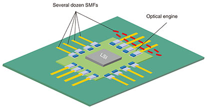
Regular Articles Vol. 21, No. 4, pp. 77–82, Apr. 2023. https://doi.org/10.53829/ntr202304ra1 A Concept of Introducing Magnetic Attraction Structure into Optical-fiber ConnectorAbstractHigh-density on-board optical connectors are necessary for next-generation optical interconnects such as co-packaged optics in datacenter networks. To break through the size limitation of current optical connectors, we proposed the concept of introducing a magnetic attraction structure into an optical-fiber connector. We previously developed simplex and multi-fiber connectors on the basis of this concept. This article reviews the design and fabrication results of our developed multi-fiber magnetic connector, which provided low-insertion losses comparable to those of conventional multi-fiber push-on connectors while achieving space-saving connection. Keywords: optical connector, magnet, optical fiber  1. IntroductionAs information technology services, such as cloud services, fifth-generation mobile communications applications, and artificial intelligence, continue to evolve, datacenter networks will demand higher-capacity data transmission. High-bandwidth optical interconnects based on high-speed optical transceivers are widely used to accommodate the growing traffic in such datacenter networks. New optical interconnects based on co-packaged optics (CPO) have been attracting attention to break through the capacity limit of conventional interconnects based on pluggable transceivers. NTT has been developing such interconnects on the basis of our co-package type optical engine as a target example of the All-Photonics Network in the Innovative Optical and Wireless Network (IOWN) [1, 2]. Figure 1 shows an example image of CPO applications in which a large-scale integration chip and multiple optical engines with fiber pigtails are placed on a board. Since several fiber pigtails should be connected efficiently to other single-mode fibers (SMFs), a high-density multi-fiber connector is necessary.
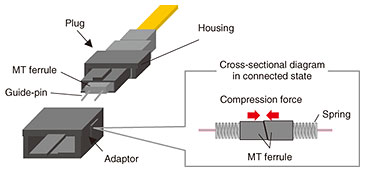
Figure 2 shows the configuration of a typical multi-fiber push-on (MPO) connector [3], which was developed by NTT and the most widely used multi-fiber optical connector. The MPO connector plug consists of a mechanically transferable (MT) ferrule into which optical fibers are precisely aligned and fixed, two guide-pins in the male plug (two guide-holes in the female plug), spring, and housing parts. When we connect these connectors via an adaptor, multiple optical fibers can be connected simultaneously with high precision by fitting the two guide pins and guide holes. Each ferrule end is obliquely polished and pressed with the spring from the rear end of the ferrule to achieve angled physical-contact (PC) connection. The connector can yield good optical characteristics with a push-pull connection but is not ideal for such applications because it is too large for on-board connections. Further size reduction of MPO connectors is limited because they require a spring and related housing parts, which are essential for applying enough compression force needed for the angled PC connection [3].
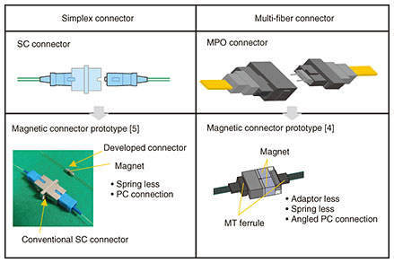
In light of the above issues, we proposed the concept of introducing a magnetic attraction structure into an optical-fiber connector to provide enough compression force by magnetic force. Our concept enables us to eliminate the need of spring and related housing parts; thus, the connector size can be miniaturized. This article introduces this concept and reviews the design and fabrication results of our developed multi-fiber magnetic connector [4], enabling an angled PC connection. 2. Concept of magnetic connectorOur concept is to use magnetic attraction as compression force applied between mated plug facets while following the conventional fiber alignment mechanism with conventional high-precision ferrules. We previously applied this concept to our simplex connector [5] and multi-fiber connector [4]. Figure 3 shows the relationships among this simplex magnetic connector prototype, our multi-fiber magnetic connector prototype, and conventional single fiber coupling (SC) and MPO connectors. To suppress Fresnel reflection at the mated facets, both conventional connectors provide a PC connection, which is achieved by the elastic deformation of the mated connector ends through the axial compression force supplied by a spring. In our magnetic connector prototype, a magnet or magnetic metal is placed around the ferrule instead of the spring, and sufficient compression force for PC is provided by the magnetic attraction force between them.
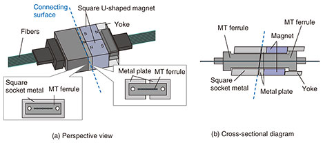
Figures 4(a) and (b) respectively show a perspective view of the first prototype of our multi-fiber magnetic connector [4] in the connected state and its cross-sectional diagram. At one side of the connector, a square magnetic-metal part with a square socket is fixed to a conventional MT ferrule (6.4 mm in width and 2.5 mm in height). At the other side, two square U-shaped magnetic-metal plates are fixed around the other MT ferrule, behind which are placed two square U-shaped magnets and magnetic-metal parts that serve as magnetic yokes. The two magnets have opposite magnetization directions, both of which are parallel to the lengthwise fiber direction. Each facet of the components is angled to be parallel to the ferrules. In this configuration, compression force between the two connectors is applied vertically to their angled facet through the magnetic force between the square-socket part and magnetic-metal plates with the two magnets.
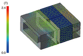
3. Magnetic simulation and mechanical designTo provide sufficient magnetic force with our magnetic multi-fiber connector while keeping the connector size as small as possible, detailed magnetic simulation is necessary since the magnetic force depends on the size, material, arrangement, and shape of the mated magnets and magnetic-metals. The ferrules should also slightly protrude from each facet of each magnetic part to ensure that the ferrule ends touch each other; thus, there should be a gap between the mated magnetic-metals. Since magnetic force is also dependent on the gap, it is necessary to design the amount of protrusion by taking the component tolerance of each part and assembly precision into account. Figure 5 shows an example of a simulated magnetic-flux density line under the basic configuration of our multi-fiber magnetic connector prototype shown in Fig. 4. In simulation, we used neodymium-based magnets and SUS430 as a magnetic-metal. As shown in the figure, the magnetic circuit is effectively confined by the yoke, and magnetic flux passes densely through the connecting surface, which indicates that magnetic attraction force is effectively applied between two mated connectors. We found that the gap should be less than about 0.09 mm if we set the target magnet force to more than 10 N, which is a standard value for conventional spring force in MPO connectors.
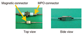
4. Fabrication resultsAs a case study, we fabricated our multi-fiber magnetic connector with a standard 12-MT ferrule in which twelve SMFs were fixed with an adhesive and the connector-end was appropriately polished to an angle of 8 degrees. We then fixed the SUS430 square-socket part to one of the ferrules and the SUS430 plates to the other so that the gap value meets the gap requirement mentioned in the previous section (0.09 mm). Figure 6 shows photographs of this connector. The connected size is sufficiently small (about 9.3 × 5 × 16 mm3), which is drastically smaller than that of MPO connectors. The insertion losses were acceptably low, less than 0.6 dB, and the average loss was 0.16 dB. The return losses of the mated connectors were also acceptably high, more than 65 dB, and confirmed angled PC connection was successfully achieved due to the magnetic force. These results indicate that the performance of our multi-fiber magnetic connector is comparable to conventional MPO connectors while enabling drastic miniaturization.
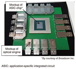
5. Conclusion and future workWe presented the concept of introducing a magnetic attraction structure into an optical-fiber connector and our developed multi-fiber magnetic connector with an angled PC connection. We will continue to develop compact optical connectors suitable for future optical interconnects with our optical engine, a mockup of which is shown in Figure 7, and contribute to the actualization of IOWN.
References
|
|||||||||||