 |
|||||||||||||||||||||||||||||
|
|
|||||||||||||||||||||||||||||
Vol. 5, No. 4, pp. 25–30, Apr. 2007. https://doi.org/10.53829/ntr200704sf3 Overview of HSDPAAbstractThe HSDPA service introduced in August 2006 was developed with the aim of achieving greater speed, lower cost, and reduced delays for W-CDMA (wideband code division multiple access). This article describes the technical characteristics of HSDPA (high-speed downlink packet access).
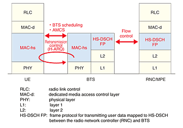
1. IntroductionNTT DoCoMo introduced the FOMA service (which stands for freedom of mobile multimedia access) in Japan in October 2001. It is a third-generation (3G) service based on wideband code division multiple access (W-CDMA). The number of FOMA subscribers surpassed the number of subscribers to the second-generation PDC (personal digital cellular) service in June 2006 and reached 30 million in November 2006. Further growth is expected to produce a smooth transition towards the third-generation mobile communication system. HSDPA (high-speed downlink packet access) satisfies demands for reduced costs, increased speed, and shorter delays for W-CDMA. It has been standardized [1] in 3GPP (3rd Generation Partnership Project) [2]. DoCoMo launched a commercial HSDPA service in August 2006. The objectives of introducing HSDPA were to increase cell throughput (increase the number of subscribers per cell and reduce the equipment cost per bit of information), increase user throughput (increase the bit rate), and reduce delays. 2. Characteristics of HSDPAThe protocol stacks and technical characteristics for equipment used in HSDPA are shown in Fig. 1. HSDPA uses MAC-hs*1 (media access control for HSDPA) retransmission control, base transceiver station (BTS) scheduling, and AMCS (adaptive modulation and coding scheme) to reduce transmission delays, improve the radio usage efficiency, and increase the bit rate over the radio channel between a BTS and a mobile terminal (UE: user equipment) [3]. Furthermore, since the bit rate over a radio channel varies in HSDPA, flow control is applied between the multimedia signal processing equipment (MPE)*2 and the BTS in order to send data in response to this variation in rate. Thus, it is also possible to perform the operations required for changing the cell used in HSDPA. These technologies are outlined below.
2.1 MAC-hs retransmission controlTo reduce transmission delays, MAC-hs retransmission control between the BTS and UE was introduced in addition to radio link control*3 retransmission control between the MPE and UE used with W-CDMA. Furthermore, previously received but undecodable data is used to synthesize data resent from the BTS by H-ARQ (hybrid automatic repeat request)*4, enabling decoding to be achieved with fewer retransmissions than required when using ARQ, which is used with radio link control retransmission control. The result is improved reception quality and greater transmission efficiency.
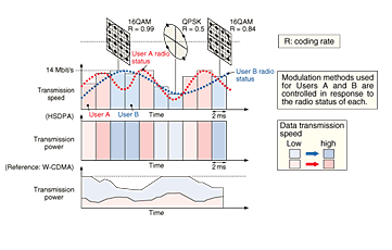
2.2 BTS scheduling and AMCSBTS scheduling and AMCS are shown in Fig. 2. While W-CDMA allocates a dedicated physical channel*5 (DPCH) to each user, HSDPA shares a high-speed physical downlink shared channel (HS PDSCH) among multiple users. W-CDMA controls the transmission power in response to variations in the radio environment in order to achieve a specified reception quality while maintaining a fixed transmission rate. Conversely, in HSDPA, the transmission power is fixed and the transmission rate is varied by using AMCS to adaptively vary the modulation method, coding rate, and the number of codes according to the radio environment. High-speed AMCS (in a minimum 2-ms cycle) permits a transmission rate that is appropriate for the radio environment, achieves a higher bit rate, and improves radio usage efficiency. Furthermore, BTS scheduling is performed at 2-ms intervals to select users who have relatively good radio environments at that instant. This improves cell throughput compared with random allocation irrespective of the radio environment. As a result, radio usage efficiency is increased.
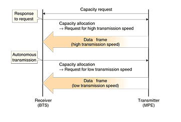
2.3 Flow controWith HSDPA, AMCS is used to vary the transmission rate in response to the radio environment, and since HS-PDSCH is also used, the transmission rate for each user is varied in response to the number of simultaneous connections. Therefore, flow control is performed to ensure that data transmission between the MPE and BTS tracks variations in bit rate over the radio channel. If flow control is not used appropriately and the transmission rate between the MPE and BTS exceeds the bit rate over the radio channel, then data exceeding the bit rate over the radio channel flows into the MAC-hs function unit of BTS, which consequently increases the queueing time in the BTS. If the queueing time in the BTS becomes excessive, it is no longer be possible for all data in the BTS buffer to be sent when the cell serving the high-speed downlink shared channel (HS-DSCH) is changed, and data is lost. This phenomenon is described in section 3.3. On the other hand, if the volume of data flowing into the MAC-hs function unit of BTS is less than the radio transmission capability, there is insufficient transmission data in the BTS, so the radio usage efficiency deteriorates. Since HSDPA has a high transmission rate, data may be lost if sufficient bandwidth is not available on the cable transmission route between the MPE and BTS, in which case flow control is also consequently performed as appropriate for the bandwidth of the transmission route. The flow control is shown in Fig. 3. Two control signals have been added to achieve it: (1) the capacity allocation signal used by the receiver (BTS) to specify the transmission rate for the transmitter (MPE) and (2) the capacity request signal used by the transmitter to request the capacity allocation signal from the receiver. When the queueing time in the BTS buffer of the receiver is short, high-rate transmission is requested via the capacity allocation signal to prevent a shortage of data in the BTS buffer. When the queueing time is long, low-rate transmission is requested via the capacity allocation signal. Then, the transmitter sends data at the transmission rate specified by the capacity allocation signal.
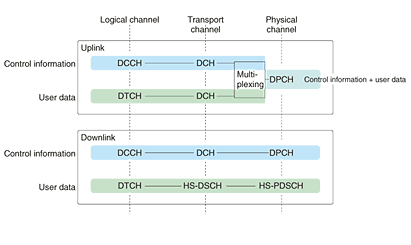
3. Mobility control with HSDPAThe channel configuration, handover, and serving HS-DSCH cell change are described below. 3.1 Channel configurationA channel configuration in which a single UE uses a radio interface during packet access with HSDPA is shown in Fig. 4. The uplink (from the UE to the network) has the same channel configuration as that used during packet access with W-CDMA. Control information is transmitted via a dedicated control channel (DCCH), which is a logical channel*6, while user data (packet data, voice, and images) is transmitted via a dedicated traffic channel (DTCH), which is also a logical channel. Each of these channels is mapped to a dedicated channel (DCH), which is a transport channel*7, and data is transmitted after it has been multiplexed onto a DPCH [4]. Conversely, the downlink (from the network to the UE) has a unique HSDPA channel configuration in which the DTCH transmitting the user data on the downlink is mapped to an HS-DSCH, which is a transport channel dedicated to each UE, and mapped to an HS-PDSCH shared between multiple HS-DSCHs on a physical channel. Since downlink control information is sent via a DPCH (a physical channel dedicated to a single user), user data and control information are sent via separate physical channels. A DPCH used with HSDPA is referred to as an associated dedicated physical channel (A-DPCH).
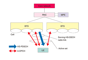
3.2 HandoverThe process of handover during packet access with HSDPA is shown in Fig. 5. A-DPCHs transmit data via multiple radio links*8. Radio links that are transmitting data on A-DPCHs are subject to handover within the base station (soft handover) and/or handover between base stations (diversity handover). The radio links that are transmitting data of a single user on these A-DPCHs and an HS-PDSCH are referred to as an active set. Data transmitted via an HS-DSCH is transmitted via an HS-PDSCH on any one radio link in an active set. While radio links transmitting data on A-DPCHs are subject to soft and/or diversity handover within an active set in this manner, a radio link that is transmitting data on an HS-PDSCH is not subject to either type of handover. A radio link that is transmitting data on an HS-PDSCH allocated to the relevant UE is referred to as the serving HS-DSCH radio link.
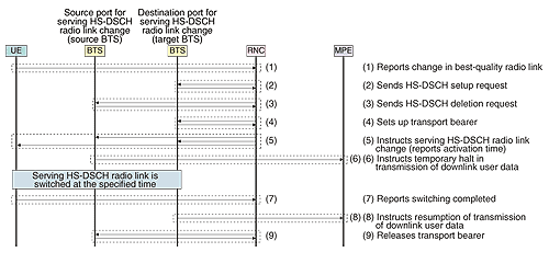
3.3 Serving HS-DSCH cell changeAs described in 3.2, the serving HS-DSCH radio link is any single radio link in an active set. To improve user throughput, the radio network controller (RNC)*9 provides control to ensure that the radio link (within the active set) for which the best reception quality is obtained at the UE is the serving HS-DSCH radio link. When the radio link within the active set providing the best reception quality changes as a result of UE movement, the serving HS-DSCH radio link must be changed accordingly. This mobility control is referred to as the serving HS-DSCH cell change [1]. The sequence for a change is shown in Fig. 6. The example shows the serving HS-DSCH radio link being switched from one BTS to another. When the reception quality of each radio link in the active set is constantly changing and a radio link is replaced with another to ensure the best reception quality, the radio link providing the best reception quality is reported by the UE ((1) in Fig. 6). Then the RNC sends an HS-DSCH setup request to the BTS (target BTS) that has the radio link providing the best reception quality (2) and sends an HS-DSCH deletion request to the BTS (source BTS) that has the current serving HS-DSCH radio link (3). The RNC then sets up a transport bearer *10 between itself and the target BTS that will be setting up the new HS-DSCH (4). The RNC then instructs the target BTS, the source BTS, and the UE to switch the serving HS-DSCH radio link (5). Since this switching is synchronized among with the target and source BTSs and the UE, its timing is reported in the relevant instruction. Furthermore, in order to prevent the loss of user data and consequent deterioration in throughput during switching, when the source BTS receives the relevant instruction, an instruction to temporarily halt the downlink transmission of user data is sent to the MPE by means of the flow control function described in section 2.3 (via the capacity allocation signal) (6). After the serving HS-DSCH radio link has been switched, the UE reports its completion to the RNC (7). The target BTS then issues an instruction to resume the transmission of user data on the downlink (via the capacity allocation signal) (8). Thus, data received by the MPE while the transmission of downlink user data was temporarily halted is also transmitted via the serving HS-DSCH radio link that has been switched to the target BTS. The transport bearer between the source BTS releasing the HS-DSCH and the RNC is then released (9), which completes the sequence.
4. ConclusionThis article described the technical characteristics related to the development of HSDPA radio network equipment: MAC-hs retransmission control, BTS scheduling, adaptive modulation and coding, flow control, and mobility control functions. References
|
|||||||||||||||||||||||||||||


