 |
|||
|
|
|||
|
Intellectual Property Vol. 5, No. 6, pp. 49–51, June 2007. https://doi.org/10.53829/ntr200706ip1 Introduction to NTT Patents: Multisector AntennaAbstractThis new irregular series will introduce a selection of NTT's patents that can be licensed. The aim is to present ones that are most likely to be useful to readers. This opening article introduces a patent on a multisector antenna, which is expected to find application in high-speed broadband wireless communication.
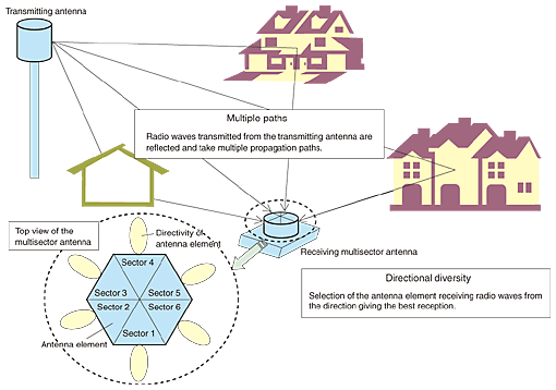
1. What is a multisector antenna?A multisector antenna uses directional planar antennas as antenna elements. These are placed in a circle to cover all directions. Only one is selected and used to give the desired directivity. 2. Multiple paths and directional diversityThe concepts of multiple paths and directional diversity are shown in Fig. 1. In a radio propagation environment for high-speed wireless communication using quasi-millimeter or millimeter waves, the presence of numerous reflected waves degrades transmission quality. There may be reflections from buildings and the ground outdoors and reflections from furniture and walls indoors. Thus, it is necessary to suppress multipath waves. A promising solution is directional diversity. This is achieved by using a multisector antenna, which segments signals received from different directions into sectors with reference to the arrival angle and selects the direction from which signals are received in the best condition.
To obtain the desired directivity with a multisector antenna, it is not necessary to rotate the antenna itself. It is only necessary to select the optimum antenna element. As a result, the antenna has a very simple structure. However, since it is composed of multiple antenna elements, a multisector antenna takes up a large area. When planar antennas are assembled in a plane, the diameter of a multisector antenna increases with the number of sectors used. 3. Patented invention and its advantageIn the patented invention introduced here, the antenna elements are not positioned in a single plane but are stacked up along the vertical central axis. Thus, the antenna is long in the vertical direction but small in diameter. This makes it possible to build a rod antenna suitable for mounting on mobile devices.
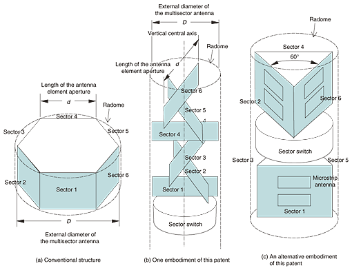
The main features of the patented multisector antenna are shown in Fig. 2. This figure shows a multisector antenna with six sectors as an example. In the conventional structure (a), six planar antenna elements are placed at the same height above the ground. The outer shape of the combined antenna is hexagonal. Let d be the length of each antenna element aperture. Then the outer diameter D of the multisector antenna is 2d. One embodiment of this patent is shown in Fig. 2(b). The antenna elements face the same directions as those in Fig. 2(a), but they are arranged vertically along the vertical central axis. This arrangement enables a reduction in the diameter D of the multisector antenna without affecting its directivity properties. In this example, D is almost equal to d. Accordingly, the outer size of the radome can be reduced, making a rod antenna suitable for mounting on a mobile device. Another embodiment of this patent is shown in Fig. 2(c). This was built experimentally for a quasi-millimeter wireless device operating at 25 GHz. This rod antenna measures 23.5 mm in diameter and 56 mm in height. Each antenna element is made up of microstrip antenna arrays mounted on a planar board. Three antenna elements were assembled to form an equilateral triangle, and two of these triangular modules were stacked one on top of the other with an angular offset of 60˚. The diameter of the multisector antenna was again reduced to about half that of a conventional planar one. Another advantage of this two-module structure is that the sector switch used to select the most appropriate sector from among the six can be placed in the center of the antenna. This makes the distance from the switch to each sector identical, which reduces any variation among the characteristics of the six sectors. The patent specification gives several examples of how the antenna elements can be arranged, including those shown in Figs. 2(b) and 2(c). 4. Application areas of the patented inventionIn quasi-millimeter or millimeter transmission, the use of a high transmission frequency increases the effect of multiple paths, makes it difficult for a power amplifier to produce high power, and increases the free-space transmission loss. Therefore, it is effective to make the antenna beam narrow to increase the gain. On the other hand, a high frequency allows the size of a multisector antenna to be reduced, making it easy to achieve high-quality transmission by switching narrow beams appropriately. In the case of mobile devices, in particular, it is difficult to point an antenna in the optimum direction all the time. An attractive solution is a multisector antenna that constantly monitors the radio wave propagation conditions and selects the antenna element pointing in the direction providing the optimal reception. In the frequency band above 20 GHz, which is expected to find wide application in the future, the wavelength is 1 cm or less. This means that even when multiple antenna elements need to be used, a multisector antenna designed according to this patent can be compact enough to be mounted on a mobile device. A multisector antenna can also be used at a base station. The use of a multisector antenna allows flexible operation of the antenna because the optimum direction cannot be selected at the time of installation. It can be selected even after installation by switching sectors according to the radio wave propagation conditions. These days, ad hoc networks, in which terminals communicate with each other directly, are being developed. In such a network, terminals need to communicate while seeking the direction of optimum radio reception in a wide range of radio wave propagation environments. The use of small and easy-to-control multisector antennas promises to be an effective solution. Licensable patents:
Inventors: Kazuhiro Uehara, Tomohiro Seki, and Kenichi Kagoshima |
|||


