 |
|||||||||||
|
|
|||||||||||
|
Global Standardization Activities Vol. 5, No. 9, pp. 31–35, Sept. 2007. https://doi.org/10.53829/ntr200709gls Standardization Trends of Optical Interfaces for Access-area Networks in ITU-TAbstractDriven by the full-scale diffusion of optical broadband access as well as wide-area Ethernet, standardization of optical interfaces to support these applications is being actively pursued. The optical-interface specification is one of the physical-layer specifications in optical communication systems. It defines transmission and reception parameters of optical signals, optical-link parameters between the transmission and reception points, and so on. This article focuses on optical interfaces for access-area networks and introduces their standardization trends with the focus on ITU-T (International Telecommunication Union Telecommunication Standardization Sector).
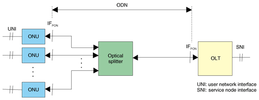
1. IntroductionCommunication networks from subscribers' homes to the network-operator's building over distances of a few kilometers to ten kilometers are called subscriber access networks. In subscriber access networks, optical fiber cables are being deployed widely to support advanced broadband access services such as the B FLET'S service provided by NTT. Another trend is the emergence of metro-access networks: communication networks that offer connections among enterprise buildings, data centers, and buildings within a college campus or in different campuses over distances of a few kilometers to several tens of kilometers. High-capacity metro-access networks are typically constructed by connecting switching equipment, such as Ethernet switches, in multiple locations via optical fiber cables. This article focuses on optical interfaces for access-area networks (subscriber access networks and metro-access networks) and introduces their standardization trends. Optical interfaces can be understood as the basis for offering interconnectivity among the equipment in these networks. 2. Study structure in ITU-T SG15In ITU-T (International Telecommunication Union Telecommunication Standardization Sector), which is the international standardization organization for telecommunication, SG (Study Group) 15 works on optical and other transport network infrastructures. Its tasks include the standardization of optical interfaces [1]. SG15 consists of 14 Questions. Q.2 has the title "Optical systems for fiber access networks" and includes the study of optical interfaces for subscriber access networks. Q.6 has the title "Characteristics of optical systems for terrestrial transport networks" and includes the study of optical interfaces for metro-access networks. Ethernet has been standardized by IEEE 802.3 Working Group. Although it was originally a standard for local area networks (LANs), recent Ethernet variants incorporate various options such as optical-interface specifications applicable to metro-access networks (1000BASE-LX, 10G-BASE-LR/ER, etc.) and specifications called "Ethernet in the First Mile" for subscriber access networks (1000BASE-PX, etc.) [2]. This article mainly focuses on ITU-T activities and trends, while making reference to appropriate IEEE standards as well. Note that ITU-T is also studying how to achieve carrier-grade Ethernet, but this article does not mention this topic because those studies mainly consider layers above the physical layer. 3. Optical interfaces for PONsThe passive optical network (PON) is a typical subscriber access network. It provides point-to-multipoint optical communication between the optical line terminal (OLT) in the network operator's building and the optical network units (ONUs) in subscribers' homes via optical fiber cables and optical splitters, as shown in Fig. 1. An optical splitter is a non-powered optical circuit that divides the optical signal. In a PON, the OLT bandwidth is shared among multiple ONUs. Optical interfaces for the PON are specified at the reference points labeled IFPON in Fig. 1.
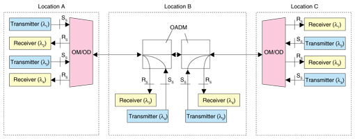
There are three major PON standards: B-PON (broadband passive optical network, ITU-T G.983 series), G-PON (Gigabit capable passive optical network, ITU-T G.984 series), and GE-PON (Gigabit Ethernet passive optical network, IEEE 802.3 1000BASE-PX series). Their maximum bandwidths are 155–622 Mbit/s, 1.25–2.5 Gbit/s, and 1.25 Gbit/s, respectively. While each of these PONs has its own features, all share the configuration and the reference points shown in Fig. 1. The optical-interface specification for PONs includes transmission parameters of optical signals, such as wavelength and power range, and reception parameters of optical signals, such as power range and required bit-error rate. ITU-T G.983.3 and G.984.2 describe the optical-interface specifications for B-PON and G-PON, respectively. The segment between the two reference points (IFPON), which consists of optical fiber and an optical splitter, is called the optical distribution network (ODN). G.983.3 and G.984.2 classify ODNs into classes A to C depending on the amount of loss (i.e., optical attenuation) in this segment, and they specify optical-interface parameters for each class. The maximum losses of classes A, B, and C ODNs are defined as 20, 25, and 30 dB, respectively. A recent addition is class B+ with a maximum loss of 28 dB. ODN loss mainly depends on the transmission distance (i.e., the length of optical fiber cables) and the splitting number of the optical splitter. For a B-PON, the maximum transmission distance is specified as 20 km and the splitting number as 16 or 32. For G-PON, the transmission distance is 20 km (with 10 km as an option) and the splitting number is 16, 32, or 64. While the relationship between the splitting number and the ODN class is not explicitly specified in order to allow some flexibility, classes A and B roughly correspond to a splitting number of 16 while classes B+ and C correspond to 32 and over. GE-PON (IEEE 802.3 1000BASE-PX series) has two classes: one is PX10 (loss under 20 dB and distance under 10 km) and the other is PX20 (loss under 24 dB and distance under 20 km). The maximum splitting number is 16 for both classes. While various other specifications such as signal-frame format are necessary in order to achieve full interconnectivity between OLTs and ONUs in a PON, the optical-interface specification can be understood as defining the basic features of each PON system such as the maximum bandwidth and the transmission distance. 4. Optical interfaces for metro-access WDM networksA simple metro-access network can be constructed by connecting a switch (e.g., an Ethernet switch) to neighboring switches via point-to-point optical fiber cables. However, it has recently become popular to multiplex several point-to-point data links into one optical fiber cable through the use of wavelength-division multiplexing (WDM). When connecting two Ethernet switches separated by a few kilometers to several tens of kilometers, one can use optical interfaces such as 1000BASE-LR (for 1.25 Gbit/s and 10 km) and 10G-BASE-LR/ER (for 10 Gbit/s and 10 or 40 km) specified in IEEE 802.3. However, these optical signals cannot be directly combined by WDM. Consequently, ITU-T has standardized optical interfaces applicable to metro-access WDM networks with a scale of several tens of kilometers. A metro-access WDM network can be configured as shown by the example in Fig. 2. An optical multiplexer/demultiplexer (OM/OD) combines and divides optical signals by wavelength, and an optical add-drop multiplexer (OADM) adds and drops some of the optical signals according to their wavelengths. In this example, wavelengths 1 and 2 (λ1 and λ2) link A and C while wavelengths 3 and 4 (λ3 and λ4) link A and B; they are also re-used between B and C. For WDM network construction, it is very useful if the optical transceivers can be obtained from multiple vendors because equipment is typically replaced and added in terms of wavelength. For this reason, ITU-T standardized optical interfaces at reference points SS and RS (see Fig. 2), namely the points before optical signals are combined and after they are divided by wavelength. Because wavelength is usually represented by λ in physics and optics, these optical interfaces are sometimes called λ interfaces or lambda interfaces.
WDM systems can be categorized into coarse WDM (CWDM) and dense WDM (DWDM) depending on the wavelength spacing. To date, CWDM systems have usually been used for metro-access networks while DWDM has been used for backbone networks. However, it is becoming popular to use DWDM for metro-access networks too because of the need to support higher bandwidths and because the costs of DWDM devices have recently fallen. Optical-interface parameters of λ interfaces for CWDM and DWDM networks are specified in ITU-T G.695 and G.698.1, respectively. In G.695 and G.698.1, optical interfaces are classified by signal bit-rate/line coding, transmission distance, and so on. Each wavelength can carry various types of data formats (e.g., Ethernet, SDH (synchronous digital hierarchy), and OTN (optical transport network)) provided that the bit-rate and line coding comply with the optical-interface type. For example, the NRZ-2.5G class can be used for any continuous data with non-return-to-zero line coding, from 622 Mbit/s to 2.67 Gbit/s, such as Gigabit Ethernet, STM-16/OC-48, and OTN1. As for the transmission distance, the short-haul class is typically defined as being around 40 km, while the long-haul class is typically for around 80 km. Note that neither G.695 nor G.698.1 assumes the use of any optical amplifiers. 5. Wavelength allocationThe above two sections described optical interfaces for PONs in subscriber access networks as well as those for metro-access WDM networks. This section summarizes how these networks use wavelengths.
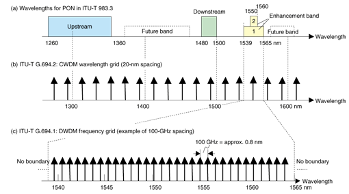
Wavelength allocation for PONs is defined in G.983.3, as shown in Fig. 3(a). Upstream and downstream transmissions use different wavelengths so that bidirectional communication is possible on a single optical fiber without signal degradation. The center wavelengths of upstream and downstream signals are specified as 1310 and 1490 nm, respectively. The wavelength range is set relatively wide (20 nm for downstream and 100 nm for upstream) considering the wavelength fluctuation of lasers created by the wide swing expected in environmental temperatures, production tolerance of lasers, availability of low-cost Fabry-Perot lasers for upstream use, and so on. The separation between upstream and downstream wavelengths is set to over 100 nm so that upstream and downstream optical signals can be combined and divided using low-cost devices. All three types of PONs described in Section 2 comply with this wavelength allocation and this commonality greatly contributes to reduced production costs. Enhancement band option 2 in Fig. 3(a) is for video distribution services over a PON [3]. Enhancement band option 1 has been defined to support an assumed DWDM extension. Future band is for future use, and its boundaries have not been specified in G.983.3 so far. The CWDM wavelength grid is specified in G.694.2 as 18 wavelength sets from 1271 to 1611 nm with 20-nm spacing, as shown in Fig. 3(b). It assumes the use of temperature-uncontrolled distributed feedback (DFB) lasers, which are suitable for high-speed, long-haul transmission because of their narrower wavelength width compared with Fabry-Perot lasers. For this reason, the wavelength spacing is relatively wide to counter the wavelength fluctuation of lasers due to temperature change. CWDM is being applied to applications where cost reduction is more important than increasing the number of wavelengths. DWDM implementation, on the other hand, is assumed to use temperature-controlled DFB lasers, where the laser wavelength is stabilized against changes in the environmental temperature. The DWDM frequency grid is specified in G.694.1. (Note that wavelength and frequency are simply related by the speed of light; 1552.52 nm corresponds to 193.1 THz for example.) The specified grids have frequency spacings of 12.5 GHz, 25 GHz, 50 GHz, and 100 GHz and above with the central frequency of 193.1 THz. An example of 100-GHz spacing is shown in Fig. 3(c). G.694.1 does not specify the boundaries, which are to be determined according to the application. 6. Future trendsAs the latest trend in subscriber access networks, some studies on next-generation access have been started. In IEEE, discussion on 10GE-PON, which has ten times the bandwidth of GE-PON, has been started. The FSAN (full service access network) forum, which submitted B-PON and G-PON proposals to ITU-T, is studying WDM functionality, reach extension, and evolution scenarios in addition to ways to increase the bandwidth [4]. The academic community has proposed and demonstrated various types of advanced optical subscriber access networks such as those with higher speed and/or CWDM/DWDM utilization. To prepare for next-generation types of access like these, ITU-T has just completed drafting a new Recommendation G.984.5 entitled "Enhancement band for Gigabit capable Optical Access Networks". It includes the characteristics of G-PON ONUs to block signals in the enhancement band as well as some updates regarding the enhancement-band definition so that the next-generation access methods can co-exist with G-PON for smooth migration in future. Regarding the λ interface, ITU-T has also just completed drafting a new Recommendation G.698.2 to provide the λ-interface parameters applicable to DWDM networks that use optical amplifiers, thus allowing the transmission distance to exceed several hundred kilometers. Future updates of G.698.1 and G.698.2 may include a narrower channel spacing than 100 GHz to increase the number of DWDM channels available. The development of the ITU-T Recommendations mentioned in this article has been driven by significant contributions from many technical experts in various countries. Given the expected growth in access-area networks, these standardization activities are expected to be actively pursued for the foreseeable future. References
|
|||||||||||


