|
|||||||||||||||||||
|
|
|||||||||||||||||||
       |
Letters Vol. 5, No. 10, pp. 61–67, Oct. 2007. https://doi.org/10.53829/ntr200710le3 Activities in the Area of Disaster Prevention Using Optical Fiber Sensing TechnologyAbstractNTT InfraNet has been working on the development of systems that use optical fiber sensing technology to identify conditions in areas such as slopes and in facilities. With more frequent natural disasters such as torrential rain and earthquakes occurring in recent years, there are strong demands for both physical and human measures to deal with disasters. These systems support initial activities to reduce damage. This article gives examples of systems provided to customers and describes the status of the development of a seafloor seismic and tsunami observation system. 
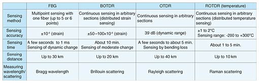
1. Optical fiber sensingOptical fiber sensing (OFS) technology does not require a power supply for the sensing part because light injected into the fiber is used for detection purposes. Thus, the system does not suffer from the effects of lightning damage or electrical induction. Quartz glass is used for high resistance to corrosion, and its low-loss properties mean that long-distance sensing is possible. Electrical sensing generally uses sensors that take measurements at a particular location (point sensing), but OFS enables distributed sensing, which allows sensing over a long range in both one and two dimensions (linear and planar sensing) depending on the sensor placement method. OFS has thus been gaining attention recently as a key technology in the monitoring of the utility infrastructure. Moreover, optical fiber cables have recently been laid along major roads and rivers, so economical monitoring systems can be made by using them as sensing lines. Thus, examples of practical application are on the rise. There are many types of OFS technology. The main ones that NTT InfraNet is working on are compared in Table 1. They use a fiber Bragg grating (FBG), optical time domain reflectometer (OTDR), Brillouin OTDR (BOTDR), and Raman OTDR (ROTDR).
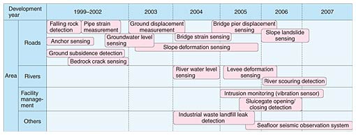
2. Developed applicationsVarious applications have been developed and the most suitable type of OFS to meet customer needs can be selected (Table 2). Some typical systems are described below.
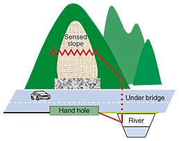
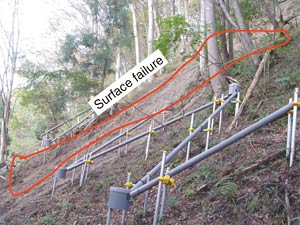
2.1 Road slope deformation monitoring system2.1.1 Background of developmentLandslides at the surface layer on slopes along roads (surface-layer landslides) frequently cause damage, but their morphologies vary greatly, making it difficult to identify where landslides will occur. NTT InfraNet is participating in the Public Works Research Institute's Joint Research on Road Slope Monitoring Systems Using Optical Fiber Sensing with the goal of achieving practical linear and planar slope deformation monitoring and is conducting sensing operations. 2.1.2 Examples of sensing systemsA monitoring system was set up in a wooded area, about 1000 m wide and 200 m high, with continuous gradual ridgelines and valleys having slopes of 20 to 30° (Fig. 1). This area has occasional small-scale landslides, so the surface layer can be expected to slide. Optical fiber sensors were installed in a 200-m section following the road on the east side of the slope, and sensing was conducted. One optical sensor (BOTDR-based) was laid in an unbroken zigzag pattern. When surface layer sliding occurs, strain is placed on the optical sensor and the BOTDR enables the deformation to be detected remotely.
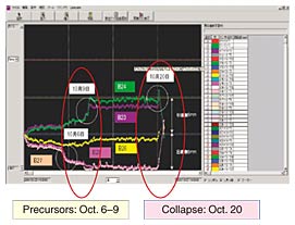
Two typhoons struck Japan in October 2004, causing damage in several areas across the country. A landslide monitoring system that was set up in late September 2004 in a particular area recorded a total of 165 mm of rain during the period of heavy rain from the time sensing began until October 20. Slight displacements occurred repeatedly each time there was rain of about 40 mm/day. But with the approach of typhoon No. 22 on October 9, cumulative rainfall reached 110 mm, and a large displacement (up to 2 to 3 mm in a 5-m sensor section) occurred (Fig. 2). After that, surface sliding occurred within the monitored area on October 20 (Photo 1). This slide was about 15 m wide and 30 m long, with soil 1 to 2 m deep sliding about 50 m along the slope to reach the highway below. The system could record the process of rapidly increasing displacement and subsequent surface slides in the torrential rains that accompanied the approach of typhoon No. 23.
2.1.3 Results of system introductionThe following improvements in road management can be expected as a result of this system being introduced.
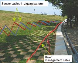
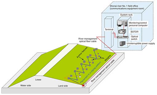
2.2. River levee monitoring system2.2.1 Background of developmentRiver administrators patrol levees regularly and also conduct special inspections in times of heavy rainfall to detect changes in the levee and take countermeasures quickly when necessary. But it is difficult and also dangerous to monitor the entire section during times of abnormally high runoff. Furthermore, detecting the situation and progress of deformation within levees is difficult to do visually. In June 2004, the Ministry of Land, Infrastructure and Transport established guidelines for river monitoring technology, clearly noting the need for water-level observation within levees to manage those levees. 2.2.2 System examplesSensing systems have been installed on the Shonai river (Aichi prefecture) and Takahashi river (Okayama prefecture), which were identified as targets for monitoring in the above-mentioned guidelines. Priority monitoring locations are (1) major levee protection areas that have a history of leaking, (2) locations of past breaks indicated by terrain classification maps etc., (3) locations in need of drainage measures, and (4) locations of levee improvement/repair construction. On the Shonai river, optical fiber sensors (using the BOTDR method) were installed in a 640-m section along the levee (Photo 2). In each sensor section, one strand of optical fiber was laid continuously in a zigzag pattern with each side being 3 m long. The monitoring system sounds an alarm if a preset value is exceeded when there is a change (slippage, etc.) in the levee caused by flooding or an earthquake etc. (Fig. 3).
For the Takahashi river, optical water-level sensors (using the FBG method) were installed in the levee. The monitoring system can accurately identify water penetration in the levee in times of abnormal runoff. 2.2.3 Effects of system introductionThis system supports visual inspection patrols. The following improvements in river management can be expected.
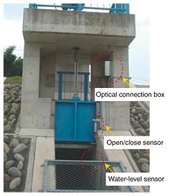
2.3 Sluicegate opening/closing detection system2.3.1 Background of developmentRiver management facilities have channels structures such as sluiceways and sluice pipes that pass through the levee (Photo 3). These control the release of water from tributaries: the gates are opened and water is released when the water level of the main river is lower than that of the tributary and the gates are closed when the main river water level is high to prevent backflow into the tributary.
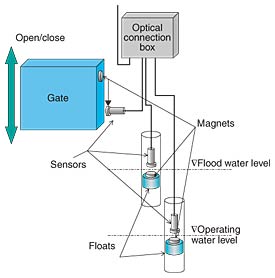
The operator needs to go to the site and read the water-level gauge to decide if the gate needs to be opened or closed. During irregular runoff, timely gate operation based on water-level changes is required for individual sluiceways and sluice pipes. The operational information is sent to the management section by means such as telephone or email. However, gate opening and closing information often cannot be gathered during irregular circumstances if the river has many such facilities. That can even cause other operators to go to the site after someone else has already performed the operation. 2.3.2 Sensing system examplesSluiceway and sluice pipe open/close detection sensors (Faraday optical sensors) using OFS technology (OTDR method) have been installed on the Shonai river (Fig. 4). With Faraday sensors, a strong reflected wave is generated when the sensor butts against a magnet, allowing realtime detection of situations such as a gate opening or closing. The following sensors were installed to detect water-level information in a step-like manner and to detect gate opening/closing information.
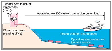
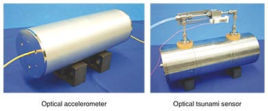
(1) Sensors were attached to floating water-level gauges and the status such as water level above a threshold is detected in steps to enable staff at the management center to judge if the gate needs to be opened or closed. (2) Sensors were attached to the side-wall and magnets were attached to the gate, and the opening/closing status is detected in real time to provide information at the center about the status of gate opening and closing performed by the operator based on this judgment. We made use of the existing river management optical fiber network from the river management office to the sluiceway and used sluice pipes as the sensing line. The system is composed of data processing personal computers, an OTDR set up in the manned river management office, and an OTDR at an unmanned office 40 km away, as well as sensors for detecting the water level and the opening/closing of five sluicegates. There was no need to construct a power source at the sluiceway, and remote control can be done from the river management office. Thus, a low-cost wide-area monitoring system could be built. 2.3.3 Effects of system introductionThe water level can be monitored remotely, and the status of gate opening and closing can be understood in real time. That allows for appropriate instructions to operators and more efficient work. 2.4 Development of seafloor seismic and tsunami observation system using OFS2.4.1 Background of developmentA seismic observation network is being set up, mainly by the Japan Meteorological Agency and the Ministry of Education, Culture, Sports, Science and Technology, and efforts are underway to use the data for disaster prevention and mitigation. However, most of the seismometers in the network are on land. The possibility of large-scale ocean trench earthquakes in areas such as Nankai, Tonankai, and offshore of Miyagi prefecture has been pointed out. Thus, there have been requests for a seafloor seismic and tsunami observation network for early detection of ocean trench earthquakes and the tsunamis that could accompany them. However, traditional seafloor seismic and tsunami observation systems are electrical, so the repeaters and multiplexing equipment must be highly reliable. This makes the system complex and expensive, which hinders progress in setting up such systems. 2.4.2 Overview of developmentOur aim is to develop FBG-based accelerometers and tsunami sensors, which will provide high reliability while greatly reducing costs. The system under development is made up of optical accelerometers, optical tsunami monitors, and undersea optical cable laid on the seabed as well as sensing equipment (FBG analyzer), a control and processing calculator, and communications equipment set up in an observation office on land. Information processed in the observation office is sent to a center via a network (Fig. 5). This system will not supply any power whatsoever to the sensors, and one strand of optical fiber can provide multiple sensors, allowing simultaneous sensing at distances of up to 100 km offshore.
We have already designed and constructed optical accelerometers and tsunami meters (Photo 4) and conducted various tests in the laboratory and at sea. Their results show that the system meets the target specifications. In July 2007, we began to install sensors under the seafloor and conduct field trials involving long-term observation. This research is a contracted development theme in the Collaborative Development of Innovative Seeds of the Japan Science and Technology Agency (JST). The Real-time Earthquake Information Consortium provides leadership and cooperation for this development.
3. Future outlookIn the future, we plan to continue proposing solutions and constructing systems that make use of the characteristics of optical fiber sensors. In this way, we hope to make people's lives safer and more secure. References
|
||||||||||||||||||