 |
|||||||||||||||||||||
|
|
|||||||||||||||||||||
|
Special Feature: NTT Technologies for the Environment and a Safe and Secure Society Vol. 6, No. 2, pp. 22–29, Feb. 2008. https://doi.org/10.53829/ntr200802sf4 Development of Highly Efficient Planar Solid Oxide Fuel CellsAbstractThis article introduces the research and development being undertaken at NTT on solid oxide fuel cells, which are expected to achieve the highest efficiency among fuel cells. Fuel cells are efficient devices for generating electric power by using the chemical reaction between a fuel and oxygen. They are not only expected to bring environmental benefits such as reduced CO2 emissions, but are also attracting the attention of distributed power generation businesses as a result of the trend towards the deregulation of the electric power industry.
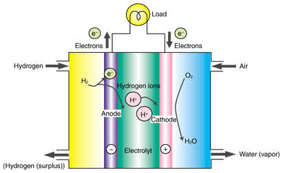
1. Overview of fuel cellsA fuel cell consists of an anode (or fuel electrode), a cathode (or air electrode), and a dense electrolyte through which only certain ions can move (Fig. 1). With this configuration, a fuel cell generates electricity through the reaction between hydrogen in the fuel and oxygen. At the anode, the hydrogen is decomposed into hydrogen ions and electrons. When an external circuit is connected between the anode and cathode, the electrons flow through this circuit. Meanwhile, the hydrogen ions travel through the electrolyte to the air electrode where they react with oxygen and electrons supplied from the external circuit to form water. As well as being an electrical terminal, each electrode plays an important role in gas diffusion between the surface and the electrode/electrolyte interface where chemical reactions take place. For this reason, the electrodes are generally required to have a porous structure. Although we have assumed here that the positive ions (hydrogen ions) move in the electrolyte, there is another type of fuel cell in which negative ions such as oxygen ions move. The term fuel cell can refer not only to electricity generating devices of this type, but also to electricity generating equipment (systems) made from such devices. To distinguish them, a single electricity generating unit is called a cell or single cell. The voltage generated by a single cell is no more than about 1 V. To obtain electrical power on a practical scale, 1 kW or more, these cells are normally connected in series to form a layered structure called a stack. The stacks are usually further combined for greater output. The term fuel cell often refers to an entire electricity generating system that consists of combined stacks and peripheral equipment such as gas supply systems.
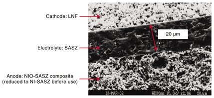
2. Solid oxide fuel cells and the need for highly efficient power generationFuel cells are regarded as clean energy devices because their only by-product is water. However, this applies only to fuel cells that run on hydrogen. At present, hydrogen is generally produced by a reforming reaction from hydrocarbons, as in the case of town gas, in which carbon dioxide (CO2) is produced. In spite of this, fuel cells are expected to be promising because they generate electricity directly from an electrochemical reaction and should therefore operate more efficiently than thermal power stations, which suffer from large energy conversion losses. If electricity can be generated more efficiently, then it should be cost-effective and beneficial in reducing the amount of CO2 emitted per unit energy. However, this is not easy to achieve. For example, we need a power generation efficiency of at least 50% to achieve lower CO2 emissions than electric power companies, taking into account thermal, hydroelectric, nuclear, and other power sources. Conventional fuel cells are not yet efficient enough to achieve this goal. Fuel cells can be broadly categorized into four types based on their electrolytes, and each type has its own characteristics. The highest electricity generation efficiency is expected to be provided by solid oxide fuel cells (SOFCs), which use an oxide ion conductor (ceramic) as their electrolyte. As a result, SOFCs have been actively researched and developed in Japan and throughout the world. However, no system has yet been developed that satisfies both the environmental and economic requirements. 3. Intermediate-temperature SOFCsConventional SOFCs generally operate at temperatures of around 1000°C (cell operating temperature). High-temperature operation is preferable for an active chemical reaction and for exhaust heat recovery and is thus expected to lead to higher efficiency. On the other hand, it imposes greater restrictions, such as on the materials that can be used for the system. For example, parts called interconnectors or separators, which connect the single cells electrically, can be made only of certain conductive ceramics. Consequently, efforts have recently been made to reduce the operating temperature. If it can be reduced to about 800°C, we should be able to use metals (heat-resistant alloys), which are cheaper and have higher electrical conductivity, thereby achieving higher electricity generation efficiency and lower costs. An SOFC that operates at around 800°C is called an intermediate-temperature SOFC. The following section introduces the current state of development related to the cells, which are the key devices in intermediate-temperature SOFC systems. 4. Development of new materials for intermediate-temperature SOFCsTo make intermediate-temperature fuel cells, we must first develop new materials. The anode is made of a composite consisting of a ceramic and metallic nickel (Ni). The metallic Ni conducts the electrons in this electrode. Therefore, the conduction is not greatly affected by decreases in the operating temperature. However, as the electrolyte and cathode are ceramics, a lower operating temperature reduces their ion and electron conductivities. Scandia (Sc2O3) stabilized zirconia (ZrO2) was considered to be a promising electrolyte material for intermediate-temperature SOFCs. However, this material is known to exhibit a crystalline phase transition at a certain temperature. Therefore, mechanical cell damage is a concern during the temperature changes that occur in the startup and/or shutdown processes. NTT has successfully managed to suppress this phase transition problem by adding small quantities of alumina (Al2O3) to scandia-stabilized zirconia. This material is referred to as SASZ below. The ion conductivity of SASZ at 800°C is about 10–1 S/cm. This is approximately the same as the conductivity of yttria (Y2O2) stabilized zirconia (YSZ), which is widely used in conventional high-temperature SOFCs, at 1000°C [1], [2]. We have also developed a new cathode material LaNi0.6Fe0.4O3 (LNF). LNF is about three times as conductive (580 S/cm) as La1–xSrxMnO3 (LSM), which is commonly used in conventional SOFCs. Furthermore, the thermal expansion coefficient of LNF is close to that of zirconia-based electrodes. This is convenient in terms of the mechanical and thermal stability of the cell as the temperature rises and falls [3], [4]. 5. Development of an anode-supported cellSOFC cells are generally categorized as having cylindrical or planar structures. The planar type is preferable for intermediate-temperature SOFCs. As shown in Fig. 2, planar cells can be further classified into electrolyte-supported cells, whose strength is maintained by the electrolyte, and electrode-supported cells (anode- or cathode-supported). Although each structure has its own benefits and drawbacks, electrode-supported cells have the advantage that the electrolyte can be made thinner because the mechanical strength is maintained by the electrode. This allows us to reduce the electrical losses in the electrolyte, resulting in a better electricity generation performance. We therefore opted for an anode-supported structure and developed cells using SASZ as the electrolyte, a composite of SASZ and metallic Ni as the anode, and LNF as the cathode [5], [6]. The anode was used as the supporting electrode because it can offer superior strength since metallic Ni conduction allows the electrode to be thicker and provides a relatively easy manufacturing process. The cell was fabricated by co-sintering. With this method, resins and solvents are added to the electrolyte and anode materials, which are in powder form, to produce clay-like substances. These are then formed into sheets with thicknesses ranging from a few micrometers to a few hundred micrometers. The sheets are then laminated together and sintered at about 1300°C to obtain a ceramic in which the electrolyte and anode are integrated (called a half-cell). The sintering is performed in air, so the anode is sintered as a composite of nickel oxide (NiO) and SASZ. The NiO is reduced to metallic Ni before the cell generates electricity. If three-layered co-sintering could be achieved that included the cathode, then it would be possible to produce a complete cell in a single sintering process. However, at a sintering temperature of 1300°C, an undesirable high-resistance layer forms between the cathode and electrolyte, so we are currently forming the cathode on the half-cell in a separate process at approximately 1000°C. A typical cross-sectional scanning electron microscope image of a cell formed as a 3-mm-diameter disk is shown in Fig. 3. The central part is the electrode. Above and below the electrode are the LNF cathode and Ni-SASZ composite anode, respectively. Even though the electrolyte is as thin as about 20 µm, it is dense enough to prevent undesirable diffusion of fuel or air and allow only ions to permeate. As can be seen, the electrodes are sintered as porous structures so that the fuel and air can easily diffuse to the reaction sites at the electrode/electrolyte interfaces. We measured the electricity generating characteristics of this cell as current-voltage (I-V) characteristics and found that they were favorable, with a maximum power output per unit area of 1.6 W/cm2 [6]. This is one of the highest values achieved for a small-scale single cell and is adequate for practical applications. Note that the evaluation of a single cell was performed in an alumina test manifold, and platinum mesh and platinum paste were used for the contact between the external measuring instrument and the electrode. This method allows us to measure the pure characteristics of the cell by eliminating as far as possible external factors such as contact resistance originating from the surface shape of the cell.
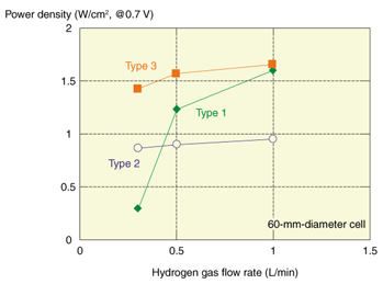
6. Larger-diameter SOFC cellsAlthough the electric power generating characteristics of the abovementioned 3-mm-diameter cell are adequate in terms of output per unit area, even under conditions where the maximum output of 1.6 W/cm2 is obtained, the actual power output is only about 1 W at most. It would therefore be necessary to use hundreds or even thousands of these 3-mm-diameter cells to achieve output power of the order of 1 kW for relatively small-scale systems such as those for residential use. When we consider that the cells will not operate at maximum output in an actual system, it is clear that many more cells would be required. This means that it is not really practical to configure systems using 3-mm-diameter cells. Therefore, the cell diameter must be increased. We have already studied increasing the cell diameter to 60 and 100 mm, and we are currently working on a 120-mm-diameter cell. When developing the 60-mm-diameter cell in particular, we encountered certain new problems related to the gas diffusion of air and fuel and to lenticular warping of the cell. As the cell size increases, it becomes harder for gas to diffuse through the entire electrode, and the reaction in the electrode becomes less efficient. This problem is common to both the anode and cathode, but it is more serious in the anode, which is designed to be thick in order to provide structural strength. Another important problem arises concerning the flatness of the cells as the size increases. Since co-sintering involves the simultaneous sintering of different materials to obtain structures that are both dense and porous, it is in principle impossible to obtain a completely flat cell. As cell warpage increases, the contact resistance between the alloy interconnectors and cells increases in the stack structure, resulting in reduced output. It has been found that the gas diffusion properties of the anode tend to depend on the average particle size of NiO powder, which is one of the raw materials used for the anode [7]. With larger NiO particle sizes, it is possible for gas to diffuse more easily through the anode, but this tends to prevent the formation of a favorable microstructure at the electrolyte/electrode interface that contributes to the electrode reaction. This behavior is illustrated in Fig. 4, which shows the power density of 60-mm-diameter cells at an output voltage of 0.7 V as a function of the hydrogen gas flow rate. With a cell that uses a fine NiO powder (type 1), a reduction in the fuel flow rate causes a large reduction in output. On the other hand, a cell that uses coarse NiO powder (type 2) does not exhibit this trend but its output is lower than that of a type 1 cell when sufficient hydrogen is supplied. In terms of increasing the efficiency of SOFCs, we need to achieve high electricity output with a suppressed supply of fuel, i.e., a high level of fuel utilization. We therefore developed another type of cell (type 3), which combines the advantages of types 1 and 2 [7]. Most of the anode consists of type 2, and it acts as the fuel diffusion layer. The type 1 anode is located near the interface with the electrolyte and is expected to function as an electrochemical active layer. The type 1 layer is made very thin to improve the gas diffusion. As expected, the power generation performance was as high as that of the type 1 cell. Moreover, as with the type 2 cell, the output characteristics hardly changed when the hydrogen flow rate was decreased (Fig. 4). Also, type 3 cell structures appear to be suitable for reducing warpage. The flatness values of 60-mm-diameter cells (types 1–3) are shown in Table 1. The amount of warpage in type 2 cells tends to be less than in type 1 cells. As most of the anode of the type 3 cell has a type 2 structure, it seems that the warpage of the type 3 cell is as small as that of type 2. The reason for the difference in flatness of these cells is related to the NiO sinterability and the layer structure. However, further investigation is required for a comprehensive understanding of this issue.
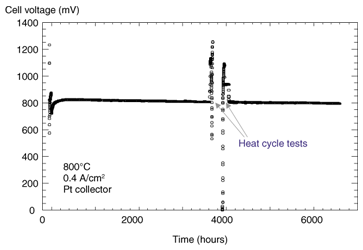
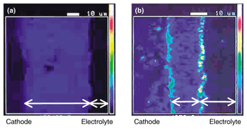
7. Long-term stability of anode-supported cellsOur studies have shown that 60-mm-diameter cells can generate adequate amounts of electricity for practical use, but if they are to be used in real systems we must ascertain their lifetime and degradation characteristics. The stability of a 60-mm-diameter cell at a constant current density of 0.4 A/cm2 is shown in Fig. 5. We confirmed long-term stability of 6000 hours; the degradation rate was 0.4% per 1000 hours. Another problem that must be considered for long-term operation is chromium poisoning: the stability of the LSM conventionally used as the air electrode is damaged by chromium (Cr) contained in the alloys of the stack materials. We therefore studied LNF and confirmed that it is less reactive with Cr at 800°C than LSM [8], [9]. Figure 6 shows the Cr distribution measured with an electron probe microanalyzer near the electrolyte/air electrode interface after electric generation tests for approximately 150 hours in an environment where Cr was present. With the LSM air electrode, a high concentration of Cr was detected at the surface and at the interface with the electrolyte. On the other hand, no Cr was detected in the LNF electrode. We can therefore expect LNF air electrodes to remain stable in the stack structure.
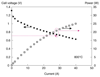
8. Current status and future prospects of stack configurationsWe are currently investigating the formation of stacks and trying to complete systems by using large-diameter cells. The power generation characteristics of a single-cell stack using a 100-mm-diameter type 3 cell are shown in Fig. 7. The single-cell stack consists of just one cell and the same components as actual multicell stacks, for example metallic interconnectors. Therefore, although this structure may not correspond exactly to multicell stacks, it allows us to evaluate the practical stack performance by taking into consideration issues such as contact resistance. Output power of 20 W was achieved at 0.7 V, which is sufficient for practical applications [7]. We have also confirmed that this structure has long-term stability (2000 hours). We will continue our studies, focusing particularly on 120-mm-diameter cells, to make cells with less warpage and higher reliability as well as inexpensive mass production techniques.
References
|
|||||||||||||||||||||


