 |
|||||||||||||
|
|
|||||||||||||
|
Selected Papers: Wide Area Ubiquitous Network Vol. 6, No. 3, pp. 21–29, Mar. 2008. https://doi.org/10.53829/ntr200803sp3 Wireless Access Systems for Wide Area Ubiquitous NetworkAbstractWide area ubiquitous networks should be able to handle more than 10,000 wireless terminals in a large wireless cell with a radius of several kilometers. However, the functions of the wireless terminals will be severely limited because of the requirements for low power consumption and low cost. Therefore, we need a sophisticated wireless access system that uses smart wireless signal processing at the wireless access point, access control, and network control techniques. In this paper, we describe the technical requirements for these technologies and briefly present the technologies that we have developed for the physical layer interface, medium access control, and network control.
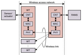
1. IntroductionSince the wide area ubiquitous network (WAUN) is a new type of network, the requirements [1] for wireless access systems, such as scalability with respect to the number of terminals, terminal mobility, and support for low-performance terminals, cannot be adequately met by current wireless access technologies. New techniques should be developed to establish a wireless access system for WAUNs. For the network infrastructure, a cellular configuration is more suitable than a multihop one considering stable operation and power consumption of wireless terminals (WTs) [1]. A fundamental link analysis [1] predicted that a 5-km cell radius could be used for outdoor WTs having transmission power of 10 mW. In this case, the reception power is extremely low, so it is hard to make the wireless access system using current wireless technologies. Therefore, to achieve these specifications, a sophisticated technology that combines wireless physical layer techniques, such as modulation/demodulation, error correction and diversity, should be developed. In particular, the wireless access point (AP) should have a sophisticated configuration and should support complex operations because the WTs themselves should have a simple configuration, simple operation, and low power consumption. Multiple access control technology that can handle tens of thousands of terminals with various service levels while suppressing the power consumption of WTs by supporting intermittent operation is important and should be developed for the wireless access system. Moreover, a network control function should be developed for stable and efficient operation of the wireless access system and to ensure terminal mobility and connectivity to the backbone network. The following sections describe the system architecture and key technologies for the WAUN wireless access system. 2. System architectureA schematic of the wireless access system is shown in Fig. 1. The wireless access system consists of two network elements: an AP and a WT. They are connected by wireless links. The AP and WT both have three functions: physical layer interface (PHY), medium access control (MAC), and network control (CNT) functions. PHY provides the wireless modulation/demodulation and transmission/reception functions. The MAC function is implemented to provide multiple access control for the wireless system, and it should support various levels of quality of service (QoS) for the ubiquitous network infrastructure. The AP is connected to the WAUN IP (Internet protocol) backbone network via a radio access network server (RANS) using CNT, and the WT connection to a terminal with a sensor or actuator is established using CNT. The CNT function also manages the PHY and MAC functions of the AP and WT. The key issues concerning these functions are described in the next section.
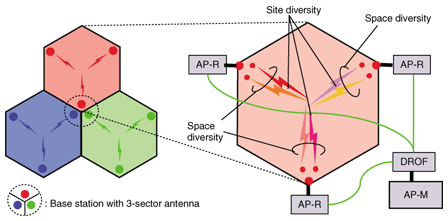
An example of the cell architecture is shown in Fig. 2. Each cell is a hexagon with a radius of a few kilometers, and the cells form a honeycomb structure. Three-sector antennas are deployed at three of the apexes of each cell, and radio-frequency (RF) signals are emitted inwards toward the center of the cell. To avoid interference from neighboring cells, different frequency channels are assigned to adjacent cells. Space and site diversity techniques are used simultaneously to achieve a high coverage probability in the cell. The PHY function is physically divided into two types of modules: the modulation/demodulation module and the RF transmission/reception module. The first module is centralized as the master equipment of the AP (AP-M) and the second is deployed with an antenna as remote equipment for the AP (AP-R). Diversity signal processing is implemented at the AP-M. The same downlink RF signals are delivered to the AP-Rs, and the uplink RF signals at the AP-Rs are collected at the AP-M. To transmit RF signals between the AP-M and AP-Rs, we use a digitized radio over fiber (DROF) subsystem [2]. In the downlink, a digitally modulated baseband RF signal at the AP-M is transmitted to an AP-R over Ethernet, and at the AP-R the received signal is converted to an analog signal and upconverted to RF. In the uplink, the received RF signal at the AP-R is downconverted to a baseband signal and digitized and then transmitted to the AP-M and digitally demodulated. The DROF subsystem can be deployed over commercially available Ethernet service and rapid provisioning can be achieved. Time and frequency synchronization between the AP-M and AP-Rs is very important in achieving diversity gain: a hardware-implemented scheme based on network time protocol is used for synchronization.
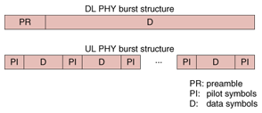
3. Key issues3.1 Physical layer interface (PHY)3.1.1 PHY requirementsThe PHY is an essential part of the wireless access system. Its requirements are summarized below. (i) Long-range transmission (large cell) The system target is a cell radius of 5 km with WT transmission power of 10 mW. (ii) Use of a modulation scheme with high frequency utilization A huge number of WTs should be supported using only limited frequency resources. (iii) Short PHY overhead Since WAUN data traffic is dominated by short packets, the PHY overhead of each packet should be as short as possible to avoid degrading the transmission efficiency. (iv) Compact, low-power-consumption WTs. WTs should be compact and have the longest possible battery life and lowest possible cost. 3.1.2 PHY functionsTo achieve the above PHY requirements, we designed the PHY functions as follows. (A) RF specifications The VHF or UHF band is selected for its low propagation and shielding loss characteristics. The WT transmission power is limited to 10 dBm, which is the limit for unlicensed use in Japan. The AP is a licensed station and can transmit higher power than the WTs. (B) Communication scheme Time division multiple access (TDMA) was selected to improve the reception sensitivity of the uplink (UL) because the receiver can use narrow-aperture synchronization in conditions where the transmission power is limited. The time division duplex (TDD) scheme is used because it allows the same WT RF circuits to be used for transmission and reception. (C) Modulation/demodulation scheme Here, π/4-shift QPSK (quadrature phase shift keying) was selected as the modulation scheme for better frequency utilization. As the demodulation scheme, differential detection is used in the WTs because it has a simple circuit, and coherent detection is used in the AP for its high sensitivity. For forward error correction, convolutional coding and soft decision Viterbi decoding were selected for their high coding gain and relatively low hardware implementation complexity. (D) PHY burst structure The PHY burst structure is shown in Fig. 3. The downlink (DL) burst consists of a preamble and data symbols. The preamble is located at the front of the DL burst and used for burst synchronization. The UL burst consists of multiple pilot symbols and data symbols. The pilot symbols are uniformly inserted into the UL burst and commonly used for burst synchronization and channel tracking for coherent detection.
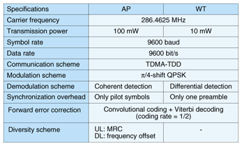
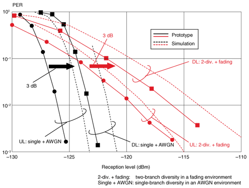
(E) DL synchronization scheme The WT's synchronization with the received signal is established by differential detection and cross-correlation of the preamble. More specifically, frequency synchronization is established by estimating the carrier frequency offset from the phase component of the cross-correlation value, and the clock and frame synchronization are established by estimating their time position from the peak of the cross-correlation value. Differential detection allows the calculation of the carrier frequency offset even when the phase shift due to the carrier frequency offset within one symbol exceeds π; this reduces the cost of the WT oscillator. Cross-correlation can detect the time positions in the case of a low carrier-to-noise ratio. Therefore, this method establishes synchronization with high accuracy within one burst. This shortens the WT receiving span and reduces the DL overhead. (F) UL reception synchronization scheme [3] Transmission automatic frequency control is used at the WTs to eliminate the UL overhead for frequency synchronization. The AP stores the entire burst within the narrow aperture, and clock and frame synchronization are established by differential detection and cross-correlation of the training symbols for channel tracking needed for coherent detection. This can also eliminate the UL overhead for the exclusive use of the clock and frame synchronization, and a high level of transmission efficiency can be achieved. (G) Diversity scheme The AP has transmission and reception diversity functions to enhance the reception sensitivity of the DL and UL in fading and shadowing environments. In the transmission and reception diversity, space and site diversity techniques are used to offset fading and shadowing, respectively. The frequency offset transmission diversity technique, which is used in the Japanese paging system, is used for the DL. With this technique, the same signals but with slightly different carrier frequencies are transmitted from the antennas, so the reception level varies with time everywhere in the cell due to interference between the RF signals from different antennas, and the cell does not have any dead spots. This technique offers a transmission diversity gain that corresponds to the number of AP antennas. There is no need to implement multiple antennas or diversity signal processing at the WT and no need for a transmission rate reduction technique, which is used in the space and time coding scheme. In the UL, the maximum ratio combining (MRC) diversity technique is used. This technique enhances the receiving diversity gain just by increasing the number of AP antennas. 3.1.3 Prototype evaluationWe developed prototypes of the AP and WTs that implemented the PHY functions (A)–(G). Their specifications are summarized in Table 1. We evaluated the reception sensitivity of the prototypes based on wired experiments through the transmission of 16-byte data packets. Single- and two-branch diversity schemes were tested in an additive white Gaussian noise (AWGN) environment and in a fading environment with independent and identically distributed Rayleigh channels, respectively. The packet error ratio (PER) characteristics are shown in Fig. 4. For reference, results of a computer simulation are also indicated by broken lines, where the noise figure was set to 6 dB, which is the value we used in designing the wireless link [4]. The required reception level is defined as the level needed to achieve a PER of 10–1 in an AWGN environment. As shown in Fig. 4, the AP reception sensitivity of the prototype was approximately -127 dBm. The simulated AP reception sensibility was -125 dBm, which enables a 5-km cell with WT transmission power of 10 mW [4]. The difference in sensitivity (about 2 dB) was mainly caused by the difference in noise figure (about 1.5 dB). Therefore, the transmission performance of the prototype can meet the requirements. Moreover, Fig. 4 shows that the DL performance was 3 dB worse than the UL performance in both the single- and two-branch diversity reception cases. These results are due to the inherent difference in sensitivity between the differential and coherent detection schemes used in the DL and UL, respectively. To achieve a 5-km cell, the AP transmission power must be 3 dB greater than the WT transmission power of 10 mW. This power level can be achieved easily because the AP-Rs can be licensed.
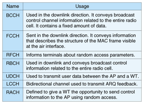
3.2 MAC functionsThe MAC protocol manages tens of thousand of WTs, maintains the communication quality using automatic repeat request (ARQ) regardless of radio link bit errors, and achieves QoS control using random access backoff window size control and dynamic slot assignment [5]. Furthermore, the MAC protocol efficiently accommodates WTs that send small amounts of data at very long intervals. It has a function for supporting intermittent reception by WTs according to the traffic situation. This reception scheme suppresses the power consumption of WTs and leads to a long battery life. 3.2.1 Logical channel and frame structureThe MAC frame structure of the wireless system is depicted in Fig. 5. Logical channels used in the MAC layer are listed in Table 2. In order to achieve good frame synchronization performance even though WTs experience poor radio link conditions, the wireless system uses TDMA/TDD in the MAC layer. The length of the MAC frame was chosen to be 9600 symbols, i.e., 1 second, considering throughput efficiency and transmission delay performance. The first part of the frame is for the downlink and the second part is for the uplink. The boundary between them changes dynamically according to the results of burst assignment scheduling, which is achieved frame by frame.
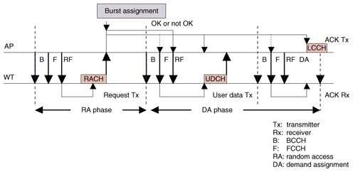
The MAC frame consists of the broadcast channel (BCCH), frame control channel (FCCH), random access feedback channel (RFCH), radio link control broadcast channel (RBCH), user data channel (UDCH), logical control channel (LCCH), and random access channel (RACH). BCCHs are used to report the attributes of the AP and are sent at the beginning of each MAC frame. FCCHs indicate the MAC frame structure, i.e., the position and length of other channels following the FCCH. RFCHs are used to send information associated with the random access, i.e., results of random access in the previous MAC frame, backoff window size of each QoS class, the position of random access slots, and the number of random access slots in the current MAC frame. RBCHs are used to broadcast radio link control messages. UDCHs are used to send user data and LCCHs are used to send MAC control information, e.g., ARQ-ACK (ACK: acknowledgment). 3.2.2 Access sequencesThe user data transmission sequence using random access and demand assignment when the user data is sent from a WT to the AP is shown in Fig. 6. In this wireless system, the AP sends a BCCH, FCCH, and RFCH in order at the beginning of a MAC frame. When a WT has user data to transmit, it receives the RFCH to determine the start position and the number of random access slots. In order to avoid collision with the RACHs of other WTs, the WT executes a backoff. The number of backoff slots in the random access is randomly selected by the WT within the range of zero to the window size. At the first random access attempt, the window size is set to the value provided by the AP as the initial backoff window size through the RFCH. After performing the backoff, the WT sends the RACH in order to request the AP to assign a UDCH for transmitting its user data. The RACH contains a MAC-ID. A unique MAC-ID is assigned to each WT and it enables the AP to identify the WTs. The length of the MAC-ID is 16 bits in this system. Therefore, the AP can manage more than 60,000 WTs.
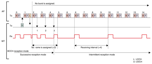
After transmitting the RACH, the WT receives the RFCH again in the next MAC frame. If the random access was successful in the previous MAC frame, the AP sends back an ACK to the WT through the RFCH. Otherwise, the AP sends nothing. When the WT fails to receive an ACK, it doubles the window size and calculates the backoff slot size according to the window size. After the backoff, the WT tries to send the RACH again. The RACH is retransmitted until it is successfully received or until the sending count reaches the predefined limit. After receiving an ACK from the AP, the WT waits for the assignment of the UDCH. When the UDCH has been assigned to the WT, it transmits the UDCH containing the user data. When the AP receives the UDCH, it sends the LCCH back with an ARQ-ACK if it receives the UDCH without any error. Otherwise, it sends the LCCH back with an ARQ-NAK (negative acknowledgment), which informs the WT of a UDCH transmission failure. 3.2.3 QoS controlThree QoS classes are defined in this system. The AP offers services based on these three QoS classes, and WTs can receive these services at the same time. The services can be distinguished by the data link control (DLC) connection, and each WT establishes three or fewer DLC connections. Moreover, in each DLC connection, ARQ is executed to correct bit errors in the radio link and to maintain the communication quality. QoS control in the uplink is achieved through AP control of the backoff window size for random access. That is, the AP decides the backoff window size appropriate for each QoS class and notifies WTs through the RFCH. WTs then execute random access using the notified backoff window size when they try to transmit their user data. When the backoff window sizes are decided in the AP, a smaller window size is assigned to the QoS class with high priority and a bigger window size is assigned to the QoS class with low priority. 3.2.4 Sleep mechanismWTs have two BCCH reception modes: successive reception and intermittent reception. The WT changes to the BCCH intermittent reception mode when there is no transmitted data. In this mode, the WT receives a BCCH only once every N times (N = 2–128). Therefore, the WT decreases its power consumption in order to achieve a longer battery life. An example of WT transition to the BCCH intermittent reception mode is shown in Fig. 7. In the case shown here, the WT is set to change to BCCH intermittent reception mode if there is no burst assignment to WT over three successive MAC frames. The WT is set to receive the BCCH once every four times in the BCCH intermittent reception mode.
3.3 Network control function3.3.1 CNT configurationThe network control function of the AP (AP-CNT) manages the AP radio link (control carrier and communication carriers) and a link to the WAUN backbone network via the RANS. WTs also have CNT (WT-CNT), and this manages WT radio links and interworks with radio and external equipment such as sensors and actuators. The AP-CNT has a TCP/IP (transmission control protocol, Internet protocol) connection to the RANS. The AP-CNT transfers user messages and control messages through this TCP/IP link. In the case of WAUN, an AP should handle a huge number of terminals, and the number of IPv4 addresses is insufficient for the number of WTs. Moreover, the WT hardware must be compact and have low power consumption, so the TCP/IP protocol stack cannot be implemented on the WT. Therefore, the AP should function as a translator between the TCP/IP-defined backbone network and the wireless access system. 3.3.2 CNT function(1) Hardware control AP-CNT controls the AP hardware. When the AP is powered on, the AP-CNT attempts to connect to the RANS. After connecting to the RANS, the AP-CNT starts broadcasting the AP information on the control carrier. At the end of the broadcast, wireless terminals can search for the AP to which they should establish a link. (2) Carrier management Since the AP can transmit multiple carriers, AP-CNT must have a management function for handling multiple carriers. An AP has one control carrier and multiple communication carriers. The control carrier transmits the operational information such as the ID of the AP. When a WT finds the AP's control carrier, it gets the ID of the AP, traffic loads of communication carriers, and other information from the BCCH. The communication carrier is used to transfer messages between terminals and the backbone network. When a WT that has selected a communication carrier requests a UDCH so that it can communicate with the backbone network, the RACH of the communication carrier is used to send the request. If the request is acceptable, the UDCH is assigned to the WT on the same carrier. The AP-CNT also manages traffic information for each carrier such as the frequency, traffic load, error information, and interference level. The WT searches for the control carrier first and synchronizes with it. Then, it selects the AP to which it should connect. (3) Terminal management AP-CNT manages WT information using a terminal management table stored in its memory. First, the WT information is set in the table when it is authenticated. Then, the elements of the table needed to establish a link are set such as the terminal ID, link ID, information pertaining to security, and terminal status. The AP obtains these elements from the backbone network when the WT is authenticated and removes them when the link assigned to the WT is purged. Several elements are updated with appropriate timing because of security issues. (4) Connection management The AP-CNT and WT-CNT make a connection between the backbone network and terminal when data arrives from the backbone network or terminals. Initially, the AP-CNT evaluates the wireless network capacity usage. The results of the evaluation are advertised on the broadcast channel to the WTs. The WT-CNT, which attempts to connect to the backbone network, can select the AP based on its traffic class and advertised traffic capacity. If the used capacity exceeds the established threshold set for generating a new link for a WT, the WT-CNT declines to generate a new link to the AP and chooses one from among other available links. Next, in the case of an upload, the WT-CNT that is trying to send an upload packet attempts to establish a link. If it has already obtained a link, it requests a communication channel. Otherwise the WT needs authentication to establish a link. Even if it has a link, subscriber authentication and ID management server in the backbone network are needed to allocate a communication channel. The subscriber authentication and ID management server evaluate whether the AP should allocate the communication channel requested by the WT. On the basis of the evaluation results, the AP-CNT permits or denies the WT access to the network through the communication channel. Only terminals that have been authenticated and that have a radio link and a communication channel can send their own data packets to the AP. In the download case, the AP-CNT waits for a data or paging message from the backbone network. When a message arrives, the AP-CNT checks the terminal management table to find the link through which the AP-CNT should transfer the message. If the terminal is found in the table, the AP-CNT allocates a communication channel for sending the message to the terminal. However, if it is not found, the AP-CNT attempts to page the terminal through the broadcast channel. A WT-CNT that monitors the broadcast channel but does not have a radio link detects this paging message. Then, the WT-CNT tries to establish a link. (5) Authentication Terminal authentication is a key issue in wireless network services because it needs to distinguish between legal and illegal terminals. In the case of WAUN, there are insufficient resources for implementing an orthodox authentication method because it is a narrowband system and has many more terminals per AP than conventional wireless systems. Therefore, the authentication method that WAUN supports should use shorter sequences to ensure low consumption of the radio resources and battery power. In addition, a message authentication code is added to each packet to enable the detection of illegal terminals. 4. ConclusionKey technical issues pertaining to WAUN wireless access systems were briefly introduced in this paper. These issues are currently being studied to achieve a more practical and economical implementation and some techniques are being investigated in the field [4]. References
|
|||||||||||||


