 |
|||||||||||||||||||||||||||||||
|
|
|||||||||||||||||||||||||||||||
|
Selected Papers: Wide Area Ubiquitous Network Vol. 6, No. 3, pp. 30–39, Mar. 2008. https://doi.org/10.53829/ntr200803sp4 Field Test Results for Wireless Access to Wide Area Ubiquitous NetworkAbstractThis paper describes field tests conducted in Tokyo to confirm the feasibility of the target wireless access conditions for NTT's wide area ubiquitous network (WAUN). The results show that the MRC (maximum ratio combining) scheme is completely feasible as a means of providing site diversity reception at the access point by using a digital radio over fiber (DROF) subsystem. In addition, we theoretically evaluated the outage probability of the system using MRC-based site diversity reception. From these results, we conclude that the design targets—a cell radius of 5 km and wireless terminal transmission power of 10 mW outdoors—can be achieved.
1. IntroductionNTT considers a wide area ubiquitous network (WAUN) to be the best way to provide public ubiquitous services [1], [2]. WAUN can support various kinds of ubiquitous services such as an automatic gas meter reading service, vending machine management service, and remote watching service for monitoring water levels in rivers, which have been hard to be implement using conventional short-range systems such as radio frequency identification (RFID) and sensor networks. Thus, a WAUN user can interact with a large number of wireless terminals (WTs) anytime and anywhere and can gather a lot of information via the WTs and/or activate them to control or manage things as desired. Therefore, the hardware and communication costs of each WT must be much lower than those of terminals used for conventional wireless networks. In particular, the wireless access cost must be much lower than in the conventional cellular system. Long-range wireless transmission techniques are needed in order to greatly reduce the cost of access points (APs). The uplink of the WAUN is the key technical issue because the transmission power of a WAUN WT is greatly limited (to reduce cost). Thus, our studies on long-range wireless transmission techniques have focused on the performance of the uplink (UL) rather than downlink (DL) [3], [4]. Our immediate goal is to achieve a cell radius of 5 km and WT transmission power of 10 mW, which is the limit for unlicensed use in Japan, in the outdoor environment. We have already conducted field tests in Kanazawa, Japan, to evaluate the feasibility of this goal [5]. The results showed that 5-km wireless links can be set up in residential and rural areas, where shadowing*1 is not severe, but not in business areas, where shadowing is severe, even if space diversity reception*2 is used at the AP. To overcome the problem of severe shadowing, we think that space diversity reception must be supported by site diversity reception*3 at the AP. The conventional approach to site diversity reception is to use the selection combining scheme [6], [7]. This selects one data sequence from some data sequences transferred from some base stations by using reliability information, such as cyclic redundancy check (CRC), signal-to-interference plus background noise power ratio (SIR), and signal strength. However, WAUN must have a lower outage probability than the conventional cellular system because it must support mainly immobile objects. Therefore, we think that the maximum ratio combining (MRC) scheme needs to be used as the site diversity reception scheme. To achieve this, our approach is to use a digital radio over fiber (DROF) subsystem [8]. It can link radio frequency (RF) components and the baseband (BB) component of the AP through an optical fiber. Specifically, it can establish time-and-frequency synchronization between the RF and BB components and transfer intermediate frequency (IF) or BB signals between them. These functions allow multiple RF components to be located far from each other, which makes possible site diversity reception based on MRC. To confirm the validity of the DROF subsystem and the feasibility of site diversity, we conducted field tests in Tokyo, Japan. First, we theoretically evaluated the feasibility of a cell radius of 5 km and WT transmission power of 10 mW. Then, we evaluated the packet loss and time-and-frequency synchronization performance of a DROF subsystem in field tests. We also evaluated the transmission performances of site diversity in field tests and found that the MRC scheme was completely feasible as a means of providing site diversity. From our results, we conclude that the AP can implement both site diversity reception based on MRC and space diversity reception based on MRC. Thus, a cell radius of 5 km and WT transmission power of 10 mW in an outdoor environment are feasible.
2. Wireless uplink designThis section introduces an example of a design for the wireless UL for WAUN. To achieve the desired cell radius of 5 km, the AP must have excellent performance in order to compensate for the low performance of the WT, which is required have a small volume, low power consumption, and low cost. There are several approaches to improving the performance of the AP: (1) Use a low frequency band and suppress propagation and diffraction losses
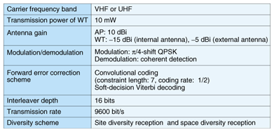
(2) Get a large antenna gain at the AP (3) Achieve a small noise figure at the AP's receiver (4) Use forward error correction (FEC) (5) Use high-gain diversity reception We considered (1)–(5) in designing the wireless system for WAUN [3], [5]. The resulting specifications are listed in Table 1. The VHF (very high frequency) or UHF (ultrahigh frequency) band was selected as the carrier frequency band because the propagation loss is relatively small and WAUN does not need a large bandwidth. We assume that the AP's antenna will be located on the rooftop of an NTT building because a larger antenna gain requires a large antenna. Thus, the AP antenna gain is set to 10 dBi, considering a practical size for an antenna using the VHF or UHF band. The WT antenna gain is set to –15 dBi for the internal antenna and –5 dBi for the external antenna. In addition, the noise figure is set to 6 dB as a value that can be achieved by locating a low-noise amplifier next to the antenna on the rooftop to compensate for loss in the feeder cable. The modulation scheme is not frequency shift keying (FSK) used in the low-power systems such as RF-ID, but π/4-shift QPSK (quadrature phase key shifting) because it can offer a higher frequency utilization efficiency than FSK and is also robust against nonlinear distortion. Coherent detection is used for the demodulation scheme to enhance the reception performance. For the FEC scheme, convolutional coding with soft decision Viterbi-decoding is used because it is used in various wireless systems such as wireless local area networks; its advantages include high coding gain and relatively low hardware implementation complexity. The transmission rate is 9600 bit/s. We think that this speed is sufficient for WAUN services. Since this bandwidth is narrow, the fading channel is flat. Therefore, an interleaver/deinterleaver scheme is used to maximize the effect of FEC gain in the flat fading environment. Packets that are longer than the Doppler cycle are expected to be yielded an FEC gain improvement due to time diversity. Furthermore, to compensate for the performance degradation in shadowing and fading environments, we use site and space diversity reception schemes at the AP.
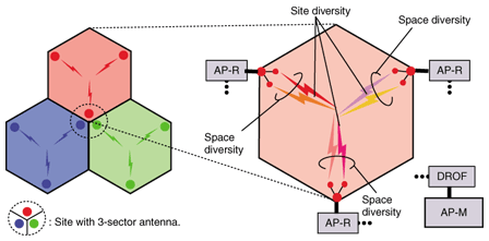
3. Theoretical evaluation for cell radius3.1 Cell configurationIn order to implement both site and space diversity reception at the AP, we use the cell configuration shown in Fig. 1. The RF components of the AP (denoted AP-R for AP-remote) are placed at three roughly equidistant sites on the edge of a cell with an angular interval of 120°. The BB component of the AP (denoted AP-M for AP-master) can be located anywhere because all AP-Rs are linked to the AP-M by DROF. Each site has 3 AP-Rs and each AP-R has a sector antenna with half the power beamwidth of 120°; each of the 3 AP-Rs in a site uses a different frequency and covers a 120° area of a different cell. This configuration can achieve three-site diversity reception without any increase in the number of buildings with AP-Rs installed on them. Moreover, space diversity reception can be used at the AP if each AP-R has multiple sector-type antennas with the same antenna direction.
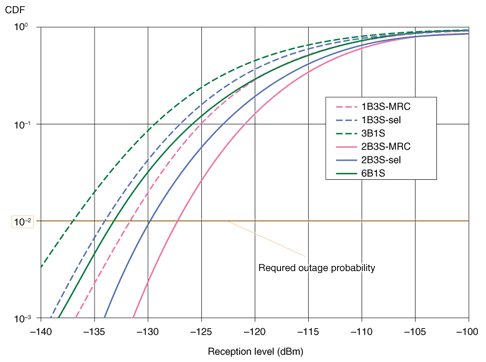
3.2 Theoretical evaluationWe theoretically evaluated the feasibility of 5-km wireless transmission with 10-mW WT transmission power by calculating the cumulative distribution function (CDF) of the reception level. We assumed that signals received at the AP-R of a site are combined using MRC, which means that the AP can implement space diversity reception. Under this assumption, we calculated the CDF of the reception levels for two different diversity reception schemes: (i) the combined signals of all sites in a cell are additionally combined using MRC (3-site MRC) and (ii) the combined signal having the highest receiving level among all sites in a cell is selected (3-site selection). (iii) Furthermore, for reference, we also calculated the CDF of the reception level when all antennas of the AP are located at the center of the cell; the AP antennas are omnidirectional and the received signals are combined using MRC (1 site). We assume that in (i) and (ii) each AP-R has either 1 or 2 antennas (with 1 or 2 branches per site using 3-site MRC (1B3S-MRC or 2B3S-MRC) or 3-site selection (1B3S-sel or 2B3S-sel)) and that in (iii) the AP has 3 or 6 antennas (3 or 6 branches per site (3B1S or 6B1S)). Note that 2B3S-MRC or 2B3S-sel means that the AP runs both site and space diversity, 1B3S-MRC or 1B3S-sel means that the AP runs only site diversity, and 3B1S or 6B1S means that the AP runs only space diversity. We assumed that the carrier frequency is 280 MHz. i.e., the VHF band. AP and WT antenna heights are assumed to be 100 and 1.5 m, respectively. The WT antenna gain is assumed to be –15 dBi (internal antenna). As the propagation model, we examined the Okumura-Hata [9], log-normal, and Rayleigh models as long-distance path, shadowing, and fading models, respectively. Note that we also conducted field research on wireless propagation in the same area of Tokyo. The propagation values identified in the field research were used for the following parameters: standard variation of the log-normal, shadowing correlation, and fading correlation. The evaluated CDFs are shown in Fig. 2. We assumed a required outage probability of 1%, which is lower than the value of about 10% for the conventional cellular network [10]. As shown in Fig. 2, the 2B3S-MRC offers 6-dB improvement over 6B1S when both configurations have the same number of antennas. Moreover, 2B3S-MRC achieves improvements of 5 and 2.5 dB compared with 1B3S-MRC and 2B3S-sel. Therefore, using both site diversity based on MRC and space diversity based on MRC can remarkably enhance the cell coverage.
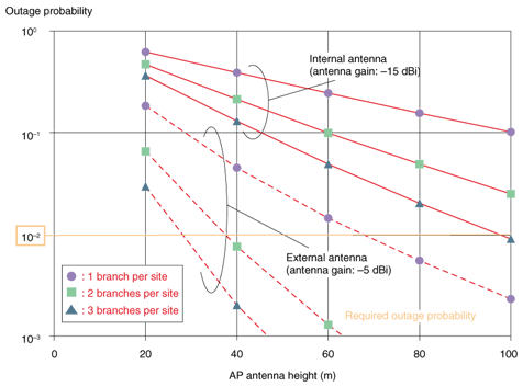
Next, we evaluated the AP antenna height required to meet the required outage probability in cell configuration (i) (3-site MRC). Specifically, we calculated the outage probability at the required reception level as a function of AP antenna height. The required reception level was set as follows. In the wireless link design, packets much shorter than the Doppler cycle cannot obtain the effect of time diversity, so the transmission performance is worse than that of long packets in a fading environment. Therefore, it is reasonable to use the transmission performance for short packets as the required reception level. The transmission performance for short packets in a fading environment matches that of additive white Gaussian noise (AWGN) because the fading channel is flat and static within a packet. Therefore, the required instantaneous reception level is defined to be –125 dBm, which is the reception level required to achieve a packet error rate (PER) of 10–1 under AWGN conditions in the wireless link design, even in a fading environment. Thus, the CDF at the required instantaneous level is defined as the outage probability. Moreover, in this evaluation, we considered each AP-R as having 1 antenna or 2 or 3 antennas (1 branch, 2B3S-MRC, or 3B3S-MRC) and WT antenna gains of –5 and –15 dBi for the external and internal antennas, respectively. The outage probability is shown as a function of AP antenna height in Fig. 3. With the external WT antenna, 2B3S-MRC and 3B3S-MRC can achieve an outage probability of 1% with AP antenna heights of 40 and 30 m, respectively, which are practical values for NTT buildings. Furthermore, with an internal WT antenna, 3B3S-MRC can achieve an outage probability of 1% with an AP antenna height of 100 m, which is practical for NTT buildings because steel towers could be erected on them. Therefore, a cell radius of 5 km and WT transmission power of 10 mW can be achieved with a cell configuration of 2B3S- or 3B3S-MRC. This means that if we implement site diversity reception based on MRC as well as space diversity reception based on MRC at the AP, we can achieve a cell radius of 5 km.
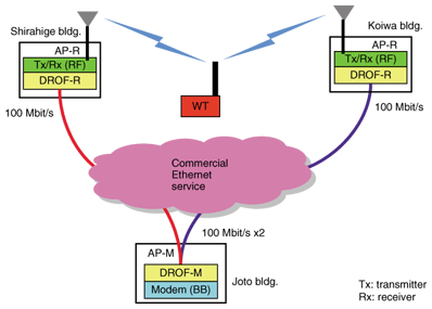
4. Field test I: DROF subsystem4.1 Test outlineWe used our prototype [5] in the field test. The DROF subsystem was used as a feeder network linking the AP-M to AP-Rs. It transfers radio BB signals between the AP-M and AP-Rs, as well as time-and-frequency reference signals. A schematic of the DROF subsystem used in the field tests is shown in Fig. 4. The same subsystem was also used in the site diversity field test, as described section 5. Two AP-Rs were located on two NTT buildings (Shirahige and Koiwa buildings) in the Tokyo metropolitan area. The AP-M was located on another NTT building (Joto building). These buildings were connected by the DROF subsystem provided over a commercial wide-area Ethernet service [8]. Traffic such as equipment control signals was also transmitted over the same network. In the DROF subsystem, the digitized radio BB signals from the radio interfaces were mapped to Ethernet packets and transmitted between the master DROF (DROF-M) and remote DROF (DROF-R) bidirectionally. The DROF-M's reference clock was fed to the AP-Rs to establish time and frequency synchronization between the DROF-M and DROF-Rs; for this purpose, hardware-implemented network time protocol was used [11]. The time and frequency synchronization of the AP-Rs allowed precise alignment of the reception timing of the RF signals captured by the AP-Rs at the AP-M; the sampling frequencies of the AP-M and AP-Rs were synchronized. Therefore, MRC-based site diversity reception could be achieved by using the DROF subsystem.
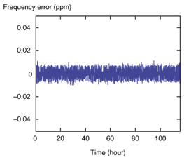
4.2 Test resultsTo confirm the validity of using a commercial Ethernet service as the DROF infrastructure, we measured the Ethernet packet transmission performance and synchronization characteristics. Packet loss in the network was very rare, and stable operation was observed for periods of more than 24 hours. Therefore, the packet transmission quality was sufficient to link the AP-M and the AP-Rs. The frequency drift observed at the Koiwa building AP-R is shown in Fig. 5. The measured minimum network delay between the AP-M and this AP-R was about 400 µs, and the delay variation in the Ethernet packet stream was around 200 µs. Under these network conditions, the regenerated frequency at the DROF-R was stable to within ±0.01 parts per million (ppm) with respect to the reference; this satisfies the frequency synchronization requirement of ±0.03 ppm. The relative time offset was also controlled to within the required time synchronization range of ±1 µs. These results verify that a commercial Ethernet service can be used to implement the DROF subsystem.
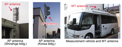
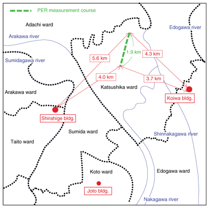
5. Field test II: site diversity reception using DROF subsystemNext, to confirm the feasibility of using the DROF subsystem to achieve site diversity reception, we evaluated its PER performances in an actual propagation environment created using the same field test configuration. 5.1 Test outlineIn the field test, the two AP-Rs and the AP-M were used to evaluate the PER performances of 2-site diversity without space diversity (1B2S) as the first step in investigating site diversity. Two AP antennas were placed on the rooftops of NTT buildings (Shirahige and Koiwa). Each antenna was a corner reflector antenna with antenna gain of 7 dBi. The antenna heights were 40 and 20 m for the Shirahige and Koiwa buildings, respectively. The WT was set in a measurement vehicle and its antenna was set on the vehicle's roof. The antenna was a dipole antenna with antenna gain of 2 dBi. Photographs of the AP antennas, measurement vehicle, and WT antenna are shown in Fig. 6. We varied the loss between the WT antenna and WT equipment by using a step attenuator to make the total system gain in this field test equal to that of the wireless link design. The WT antenna was the internal type with antenna gain of –15 dBi. The measurement vehicle was driven around Tokyo while a fixed quantity of data (16 bytes) was transferred with and without site diversity reception based on MRC. The case without site diversity is denoted “single”. A map of the field test area is shown in Fig. 7. The actual test course is indicated by the dashed green line. The test course was selected so as to roughly equalize the reception levels at the two buildings.
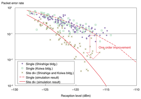
5.2 Test resultsThe PER performances as a function of reception level are shown in Fig. 8. Here, the reception level for site diversity is defined to be the mean value for the two buildings. For reference, the figure also shows PER performances plots of MRC-based site diversity and single (evaluated by computer simulation) by solid and dashed lines, respectively. The noise figure was assumed to be 6 dB and independent and identically distributed (i.i.d.) Rayleigh fading channels with the same power on all paths were used as the fading model. As can be seen in Fig. 8, the measured PER performances basically matched those obtained by computer simulation for both the site diversity and single cases. This confirms that site-diversity-reception-based DROF can offer the theoretical MRC diversity gain in an actual propagation environment. Site diversity can offer a PER one order lower than single. The results confirm the feasibility of site diversity based on the DROF subsystem and show that the MRC scheme is completely feasible as a means of providing site diversity in conjunction with the DROF subsystem. From the above results, we conclude that an AP can run site diversity reception based on MRC as well as space diversity reception based on MRC, so the cell radius of 5 km with transmission power of 10 mW is feasible.
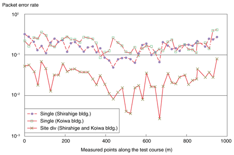
The PER performances as a function of measurement position are shown in Fig. 9. The horizontal axis is the distance from the southernmost point along the test course. As shown in this figure, site diversity improved the PER performance over that offered by single at each building at all points. This means that site diversity reception based on DROF can enhance the PER performance compared with that of ideal inter-cell handover. That is, in an actual environment, cells that offer site diversity have a better cell coverage than those that do not, such as those in the conventional cell configuration.
6. ConclusionWe think that a cell radius of 5 km with WT transmission power of 10 mW outdoors is needed to ensure that the cost of access to the WAUN is low. We theoretical clarified that this cell radius can be achieved if the MRC scheme is used to implement site diversity reception as well as space diversity reception at the AP. The results of field tests conducted in Tokyo confirmed the validity of the DROF subsystem used to achieve site diversity. They showed that, even when implemented on a commercial Ethernet service, the DROF subsystem can link AP-Rs to the AP-M and that the MRC scheme is completely feasible as a means of providing site diversity in conjunction with the DROF subsystem. On the basis of these results, we conclude that the AP can implement both site and space diversity reception based on MRC and that a cell radius of 5 km with WT transmission power of 10 mW in the outdoor environment can be achieved. References
|
|||||||||||||||||||||||||||||||


