 |
|||||||||||
|
|
|||||||||||
|
Letters Vol. 6, No. 5, pp. 28–33, May 2008. https://doi.org/10.53829/ntr200805le2 Platform Technologies of IP Optical Traffic Engineering ServerAbstractThis article describes the platform technologies of an Internet protocol (IP) and optical traffic engineering (TE) server, which performs traffic control in cooperation with IP routers and optical cross-connects in both IP networks and optical backbone networks. This IP optical TE server responds flexibly to unexpected changes in traffic demand and restores network connectivity quickly if a system failure or natural disaster occurs while network resources are being utilized.
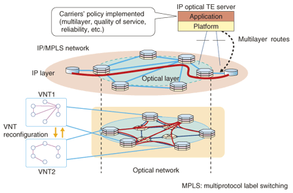
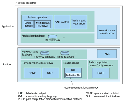
1. IntroductionThe network is expected to be flexible enough to handle unexpected changes in traffic demand and to be robust against network failures or natural disasters that occur while network resources are being utilized. NTT Network Service Systems Laboratories has been developing an Internet protocol (IP) and optical traffic engineering (TE) server (IP optical TE server), which performs traffic control in cooperation with IP routers and optical cross-connects in both IP networks and optical backbone networks [1]–[3]. The traffic control is called multilayer traffic engineering. This article introduces the server's functions and its platform technologies. 2. Functions of the IP optical TE serverMultilayer traffic engineering enables us to utilize network resources in IP and optical networks. As shown in Fig. 1, this server manages network resources of both networks and provides multilayer routes. In addition, it reconfigures a virtual network topology (VNT) consisting of several optical paths in response to traffic demand changes and network failures. The server's functions consist of (1) multilayer and multidomain path computation, (2) VNT control, (3) traffic matrix estimation, and (4) network status visualization. The software structure of the server is shown in Fig. 2.
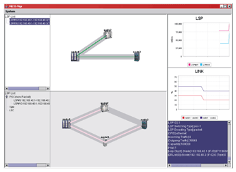
(1) Multilayer and multidomain path computation Multilayer path computation: let us consider computing a route between a source router and a destination router in an IP/optical network. There are two possible ways to do this: by a single-layer or multilayer path computation. In the single-layer path computation, only IP links that have already been established are considered. They may be optical paths. On the other hand, in the multilayer path computation, the possibility of new IP links, which are optical paths that will be established later, are considered as well as previously established ones. For example, if the source router is not connected to the destination router in the current IP topology, the IP optical TE server may decide to establish a new optical path for the requested end-to-end packet path based on both IP and optical network resources. The calculation takes into account constraints such as bandwidth, delay, link attributes, inclusive/exclusive routes, and protection class. The multilayer route that is finally selected also depends on the carrier's policy. For example, one policy might try to find available existing optical paths as much as possible, while another might try to establish a new optical path in order to minimize the number of hops between source and destination routers. Multidomain path computation: in a large-scale network, it is difficult to operate a single domain, where a domain means an area or autonomous system, due to the limitations of routing protocol scalability. A large-scale network is operated as multiple domains. Since an IP optical TE server cannot handle all the domains, several such servers are distributed throughout the network and they communicate with each other to provide an end-to-end path route. (2) VNT reconfiguration The IP optical TE server can reconfigure the VNT in response to a traffic demand change, network failure, or topology change or under the control of an operator. (3) Traffic matrix estimation The VNT design algorithm uses a traffic matrix as input information. Each element of the traffic matrix is the traffic volume between a pair of border routers. As the network increases, the number of border routers increases and it becomes difficult to measure all the traffic volumes between border routers. In addition, in the case of IP packet networks, it also becomes difficult to analyze the IP headers of all the IP packets to determine their destination border routes. Therefore, the traffic matrix derivation method must be scalable in terms of network size. Our approach is to estimate the traffic matrix based on the traffic volume passing through IP links (which are optical paths) and on IP/MPLS routing information, instead of directly measuring each traffic volume between border routers. We implemented our traffic matrix estimation function in the IP optical TE server. The traffic matrix estimation process consists of the following three steps. In step 1, the traffic volume passing through IP links is retrieved using SNMP (simple network management protocol) from the interface management information base (MIB). In step 2, the traffic matrix is estimated using the retrieved traffic volume and the IP/MPLS routing information. This estimation reduces the complexity of the traffic measurement, making it proportional to the number of IP links, whereas in the conventional approach it is proportional to the number of border router pairs. As a result, VNT reconfiguration is possible even when the network size is large. (4) Virtualization of network status A network operator can efficiently control and manage networks by visualizing the multilayer network status. The visualization function displays the topology of each layer and the network status. A schematic screen image is shown in Fig. 3. It provides a realtime display of the physical network topology, IP network topology (VNT), traffic volume passing through optical paths and MPLS paths, and lists of MPLS and optical paths including their routes and attributes.
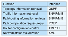
3. Platform technologies for the IP optical TE serverThe IP optical TE server consists of a platform part and an application part. The platform part provides common functions and related interfaces that support application-specific functions for the application part. The server's functions and interfaces are listed in Table 1. The platform supports the OSPF (open shortest path first) protocol to collect topology information, SNMP/MIB to retrieve traffic information, and PCEP (path computation element communication protocol) [4] for path computation request and reply. It also supports a command line interface (CLI) to configure and control routers. As much as possible, this server uses standardized interfaces to routers, such as OSPF, SNMP, and PCEP.
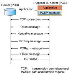
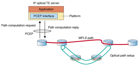
PCEP is a protocol for communication between a path computation client (PCC) and a path computation element (PCE), or between two PCEs. The communication consists mainly of path computation requests and path computation replies as well as notifications and error messages. Examples of PCEP message sequences are shown in Fig. 4. PCEP lets us separate a path computation function that was implemented in routers from the routers so that network providers can operate their networks with their own policies. It is currently being standardized by network operators and vendors, including NTT. As shown in Fig. 5, multilayer TE is performed by communication between the IP optical TE server and commercial routers.
Information that is directly collected from a network is stored in the network status database in the platform part of the IP optical TE server. On the other hand, information that is processed in the network status database and used directly for an application is stored in the application database in the application part. To support network status visualization, topology and traffic data is stored in the topology database and traffic database, respectively. After the data format has been transformed to extensible markup language (XML) format in the platform part, the data is sent to the function block for network status visualization. This makes it easy to locate the visualization function block remotely away from the main body of the server. The CLI function block for configuring and controlling routers is dependent on the types of network equipment. The implementation of the platform part eliminates the network equipment dependency by using definition files. When software in network equipment is updated or when the network consists of different types of equipment, we only have to change the definition files. 4. Future developmentIn the future, we will perform experiments on the functions of the IP optical TE server considering operation and control scenarios that may be used in practice. References
|
|||||||||||


