|
|||||
|
|
|||||
       |
Special Feature on Technical Solutions to Real-world Problems Vol. 6, No. 11, pp. 31–34, Nov. 2008. https://doi.org/10.53829/ntr200811sf2 Effective Troubleshooting Tools for IP SystemsAbstractThis article introduces packet-capturing network taps that are easy to use while costing less than commercially available ones. The location of a fault occurring in the provision of IP (Internet protocol) services such as Hikari Denwa (IP phone) can be effectively determined by capturing packets and analyzing the packet sequence, and the Technical Assistance & Support Center at NTT East has been developing a variety of troubleshooting tools for this purpose. 
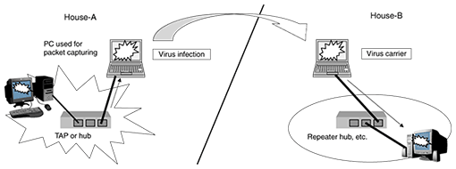
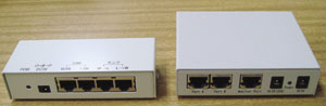
1. BackgroundCapturing packets and analyzing their sequence is an effective means of analyzing faults in Hikari Denwa (IP phone) or other IP (Internet protocol) services. This process of capturing packets requires the use of a test access point (TAP*) that can cut into the circuit to be monitored, duplicate the packets, and deliver them to the capture devices. Although packet duplication can also be performed by commercial repeater hubs or switching hubs with a port-mirroring function, packets transmitted by personal computers (PCs) used for packet capturing here will also be transmitted to the circuit targeted for measurement. This means that a packet-capturing PC infected with a virus could act as a virus carrier (Fig. 1). Because repeater hubs are almost disappearing from the market, which is making it difficult to obtain devices that can be used as TAPs at a reasonable price, we developed two types of TAPs—a repeater type and switch type—that can eliminate concerns about virus transmittal (Fig. 2).
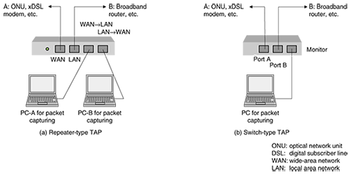
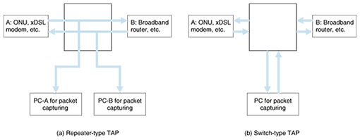
2. Usefulness of packet capturingWhen a fault is reported by a customer, it is not uncommon for the broadband router, VoIP (voice over IP) adapter, or another device to be simply replaced without a detailed investigation being performed at the customer's residence. This approach can solve the problem, but unnecessary costs could be controlled if the cause of the problem were determined and dealt with accordingly. Fault analysis in an IP system begins with the capturing of packets to check the state of packets flowing in the system. Packet-capture software can check, for example, whether TCP (transmission control protocol) retransmission of lost packets is occurring, whether RTP (real-time protocol) packets including voice data in IP-phone services such as Hikari Denwa are being lost, and whether the order of SIP (session initiation protocol) packets follows a regular pattern. In addition to commercially available packet-capture products, there is also software like Wireshark that can be used under a GNU General Public License (GNU GPL) and has functions as good as those of commercial products. However, to make full use of such software, the user must be knowledgeable about the Internet and associated protocols. To ease this requirement, the Technical Assistance & Support Center has developed a product called the Hikari Denwa Monitor Tool to be used in combination with a TAP to troubleshoot Hikari Denwa services. This tool can detect whether a SIP sequence is normal or if voice packets are being lost, and it can capture packets with a single click. Captured files have been designed to be compatible with Wireshark so that more detailed analysis can be performed if desired. 3. Functions of developed productsThe most common type of TAP used up to now outputs monitor packets for each of the directions in which packets are flowing. This type of TAP requires two interfaces to capture packets and requires sequence checking after the data obtained by packet capturing has been saved as a single file. Alternatively, if only one interface can be used to capture packets, as in a switch-type TAP, the handling of packet-capture data can be much easier. However, if wire-speed packets are flowing in both directions, the system will be hard pressed to output all the packets to the monitor port, so some packets may be lost within the TAP. In light of the above, we developed two types of switch-type TAPs that are as easy to handle as conventional repeater-type TAPs. Examples of connecting these two types of TAPs are shown in Fig. 3.
3.1 Repeater-type TAPOne way of reading packets is to simply tap an Ethernet cable by using a parallel connection. With this method, however, electrical terminating conditions at the ports can affect the waveform of the circuit and may even disturb the stability of the Ethernet link in the worst case scenario. The repeater-type TAP that we developed connects the branched line to the monitor port via a buffer amplifier, making it difficult for the circuit being measured to be affected by such terminating conditions. The repeater-type TAP has the following features. (1) Since packets are not processed as digital signals, the device outputs signals from the Ethernet cables themselves (including noise and waveform distortion) to the monitor-port side. The system conveys Ethernet link pulses by delivering signals from the equipment connected to the monitor line directly to the monitor port (Fig. 4).
(2) As the uplink and downlink signals are each output to a separate port, the port that individual packets are arriving from can be physically determined and information about packet arrival times can be saved. (3) Considering that a power outlet may not be readily available at the actual site where packets are to be captured, the TAP has been designed to accept power from a PC's USB (universal serial bus) port in addition to an AC adaptor. Signals between the WAN (wide area network) and LAN (local area network) ports may continue to be transmitted even if power to the TAP unit is cut off. 3.2 Switch-type TAPA 3-port switching hub equipped with a mirror port is a switch-type TAP. In contrast to an ordinary switching hub, a switch-type TAP can also forward undersize and oversize packets as well as packets with a frame check sequence error. This enables the monitor PC to detect malformed packets. The switch-type TAP has the following features. (1) Supports VLAN (virtual local area network) tagging and is set beforehand with a VID (VLAN identification number) in the range from 1 to 4096. It is also set to transfer bridge PDU (protocol data unit) packets with MAC (media access control) addresses beginning with 01-80-C2. (2) Terminates electrical signals from other devices (Fig. 4). For this reason, the TAP unit is equipped with a DIP (dual inline package) switch to simplify the setting of automatic negotiation at a port, 10/100 Mbit/s, and full/half duplex. In addition, link states are indicated by light emitting diodes to enable the user to check for connection-mode inconsistencies. (3) Enables power to be supplied from an AC adaptor or a USB port the same as in the repeater-type TAP. However, if power to the unit is cut, transmissions by the circuit being measured will be halted. For this reason, reliability can be raised by using the two power connectors on the main unit simultaneously to provide power from two channels. 4. Future developmentsThe number of IP-related faults is estimated to increase as B FLET'S broadband services continue to grow. The TAP devices that we developed and introduced here can capture packets and troubleshoot problems on-site at the residence of a customer reporting a fault and can make fault-repair work more efficient while raising the quality of maintenance. |
||||