|
|||||||||||||||||||||||||||||||||||||||||||||||||||||||||||||||||||||||||||||||||||||||||||||||||||||||
|
|
|||||||||||||||||||||||||||||||||||||||||||||||||||||||||||||||||||||||||||||||||||||||||||||||||||||||
       |
Special Feature: NGN Mobile Communication Technologies for Large-capacity and High-efficiency Communications in the Flat-rate Era Vol. 6, No. 11, pp. 19–26, Nov. 2008. https://doi.org/10.53829/ntr200811sf6 Fourth-generation Mobile Communication Using MIMO High-speed Packet TransmissionAbstractAn ultrahigh-speed packet transmission experiment for achieving a transmission data rate of approximately 5 Gbit/s (spectral efficiency of 50 bit/s/Hz) was performed using a 100-MHz channel bandwidth in broadband packet radio access. The spectrum efficiency of 50 bit/s/Hz approaches the upper limit in cellular environments near a cell site, i.e., base station, taking into account inter-cell interference. This article gives an overview of the technology, describes the experimental configuration, and presents the results of a field experiment. 
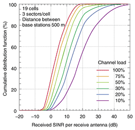
1. IntroductionThe transmission data rate targeted by fourth-generation (4G) mobile communication systems called IMT-Advanced is 100 Mbit/s or greater in a cellular environment having a wide coverage area with high-mobility users and 1 Gbit/s or greater in an indoor or hotspot area with low-mobility users [1]. In previous field experiments using VSF-Spread OFDM*1 radio access (VSF*2: variable spreading factor; OFDM*3: orthogonal frequency division multiplexing) with a channel bandwidth of 100 MHz, we achieved ultrahigh-speed packet transmission with a throughput*4 of 1 Gbit/s (spectral efficiency*5 of 10 bit/s/Hz). In those experiments, we used multiple-input multiple-output (MIMO) multiplexing consisting of four transmit/receive antennas at distances of up to 300 m from the base station under mostly non-line-of-sight conditions [2]. In Europe, the WINNER (Wireless World Initiative New Radio)*6 research forum has set the target value for peak spectral efficiency in an isolated cell environment as 25 bit/s/Hz as a system requirement for next-generation mobile communications [3]. In this regard, we have also achieved an ultrahigh-speed packet transmission data rate of 2.5 Gbit/s (spectral efficiency of 25 bit/s/Hz) in an actual outdoor propagation environment featuring mobile terminal speeds of 5 to 20 km/h through the use of 6 transmit/receive antennas, 64QAM (quadrature amplitude modulation)*7, and turbo coding*8 with a channel coding rate*9 of R = 8/9 [4]. In packet transmission, the maximum transmission data rate typically corresponds to the peak throughput per cell. It is therefore important that we investigate the maximum achievable transmission data rate since raising the maximum transmission data rate for one user increases the number of users that can be accommodated by high-speed transmission. In a completely isolated cell environment in which interference from neighboring cells is nonexistent, the maximum transmission data rate can be raised without limit by increasing the number of transmit/receive antennas and the transmission power. In a multi-cell environment, however, increasing the number of antennas and transmission power also increases the amount of interference from neighboring cells. The maximum achievable transmission data rate is therefore determined by the received signal-to-interference-plus-noise-power ratio (SINR)*10, which takes inter-cell interference into account. We simulated a multi-cell environment with 19 cells (3 sectors per cell) with base station transmission power of 20 W and a distance between base stations of 500 m with the volume of traffic in neighboring cells (channel load) as a parameter. The cumulative distribution function of received SINR obtained from this simulation is shown in Fig. 1. These results show that the distribution of received SINR improves as channel load becomes smaller. But it can also be seen that received SINR at nearly all locations within a cell is no more than approximately 30 dB even in the case of a small channel load. We can therefore consider the maximum received SINR in a cellular environment to be approximately 30 dB, assuming a low-channel-load case. By performing computer simulations under the condition of a received SINR of 30 dB, we found that spectral efficiency of approximately 50 bit/s/Hz can be achieved.
In this article, we give an overview of the technology, describe the experimental configuration, and present the results of an ultrahigh-speed packet transmission field experiment using VSF-Spread OFDM radio access with a 100-MHz channel bandwidth for achieving a transmission data rate of approximately 5 Gbit/s (spectral efficiency of 50 bit/s/Hz), which is practically the ultimate data rate taking into account the inter-cell interference.
2. Technologies for 50-bit/s/Hz ultrahigh spectral efficiencyWe applied the following technologies for achieving ultrahigh spectral efficiency of approximately 50 bit/s/Hz.
The application of technologies 1) and 2) resulted in a transmission data rate of 4.915 Gbit/s (excluding the pilot signal and other overheads) in OFDM radio access with a channel bandwidth of 100 MHz. The application of high-accuracy signal separation technology 3) could significantly decrease the required received SINR compared with other signal separation methods. In this signal separation method, to reduce the computational complexity of MLD, which is particularly high when a higher data modulation scheme is used, we applied adaptive selection of surviving symbol replica candidates (ASESS)*12 [5], a method that we previously proposed using reliability information of symbol replica candidates*13, to complexity-reduced MLD with QR decomposition*14 and the M-algorithm*15 (QRM-MLD)*16 [6]. The QRM-MLD method using ASESS can greatly reduce computational complexity with almost no deterioration in throughput. This is achieved by decreasing the number of Euclidean distance*17 calculations required for signal separation by using reliability information for each symbol obtained simply by symbol*18 ranking using quadrant detection*19. When a transmission data rate of 5 Gbit/s is achieved using radio transmission technologies 1) to 3) above, QRM-MLD with ASESS can reduce the computational complexity to approximately 1/(2×1017) times that of MLD without computation-reduction measures and to approximately 1/15 that of the original QRM-MLD method.
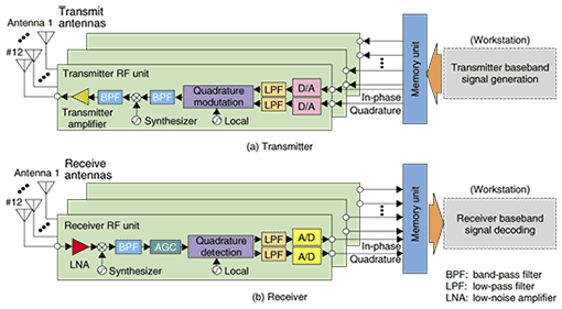
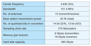
3. Structure of MIMO multiplexing transceiversThe configuration of the experimental transmitter and receiver equipment that we constructed is shown in Fig. 2. The carrier frequency and bandwidth are 4.635 GHz and 101.4 MHz, respectively. Each transmitter (receiver) has 12 antennas, each consisting of a memory unit and radio unit, the latter including a digital-to-analog (D/A) (analog-to-digital (A/D)) converter. In this experimental system, transmitted signal generation before the D/A conversion at the transmitter and received signal demodulation after A/D conversion at the receiver are done offline by a workstation. However, because actual radio-frequency (RF) transceivers are used for the signal transmission, the transmission performance is the same as for realtime signal transmission. The basic specifications of the RF unit are given in Table 1 and those of the baseband signal processing unit are given in Table 2.
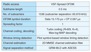
The transmitter consists of a workstation equipped with a 480-Gbyte hard disk, a memory unit with 9 Gbyte of memory per branch*20, a 14-bit D/A converter, intermediate frequency (IF)*21 and RF transmission circuits, and 12 branches of transmit antennas. First, the workstation turbo codes and bit interleaves*22 the binary information bit sequence (constraint length*23= 4 bits; R = 8/9) and then performs 64QAM data modulation mapping. It then applies a serial-to-parallel conversion to the transmit symbol sequence resulting from data modulation, placing it onto 1536 subcarriers. Next, it time-multiplexes quadrature pilot symbols*24 characteristic of the transmit antennas into subframes (subframe length: 0.5 ms) and generates a symbol sequence for each transmit antenna. The symbol sequence is converted to OFDM symbols (effective symbol length: 15.170 µs) by a 2048-point inverse fast Fourier transform (IFFT)*25 and adds a cyclic prefix (CP)*26 with a duration of 2.067 µs. The baseband modulated signal of the in-phase and quadrature components*27 after CP insertion is now stored in the memory unit of the transmitter. D/A conversion is applied to the transmitted signals at a sampling rate of 270 Msample/s followed by quadrature modulation, conversion to an RF signal, and transmission from each antenna. The receiver consists of 12 branches of receive antennas, RF and IF receiver circuits, a 12-bit A/D converter, 18 Gbyte of memory per branch, and a workstation equipped with a 480-Gbyte hard disk. In the IF band, the received signals are linearly amplified by an automatic gain control (AGC) amplifier, and then quadrature detection and A/D conversion are performed. The baseband modulated received signal of the in-phase and quadrature components is now stored in the receiver's large-capacity memory. Next, the workstation takes this digital signal and performs fast Fourier transform (FFT)*28 window-timing*29 detection. Then, after performing CP removal, it separates the signal into the components of each subcarrier. Following this, the channel estimation value*30 for each subcarrier is estimated by two-dimensional minimum mean square error (MMSE) channel estimation*31 [7], and in the signal-separation unit, signal detection is performed by QRM-MLD with ASESS using these channel estimation values. Next, to perform soft-decision*32 turbo decoding, the workstation calculates a log likelihood ratio (LLR)*33 [8] for each bit from the signal output from the signal-separation unit, and after performing deinterleaving*22, it inputs the signal into a turbo decoder (max-log-MAP decoding)*34 and recovers the transmit signal sequence.
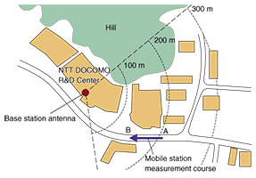
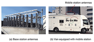
4. Field experiment resultsThe field experiment was conducted on the measurement course, shown in Fig. 3, located in the Yokosuka Research Park district of Yokosuka City, Kanagawa prefecture, Japan. The base station antennas and the measurement van equipped with mobile station antennas used in the field experiment are shown in Photo 1. The transmit antenna at the base station was a 12-branch sectored-beam antenna*35 with a 3-dB width of 90° in azimuth installed at a height of approximately 26 m. The transmission power and antenna gain of each antenna were 20 W and 19 dBi, respectively, and antennas were linearly arranged with an adjacent antenna separation of 70 cm (equivalent to approximately 11 wavelengths for the carrier frequency of 4.635 GHz). The mobile station used 12 dipole antennas*36 installed in a row at a height of approximately 3.5 m. The antenna gain was 2 dBi and the separation between adjacent receive antennas was set to 20 cm (equivalent to approximately 3.1 wavelengths). In the experiment, the van was driven along the measurement course at an average speed of approximately 10 km/h, and the distance from the transmitter ranged from 150 to 200 m. The majority of the course was in the non-line-of-sight condition because there were office buildings, approximately three to six stories high, between the transmitter and receiver.
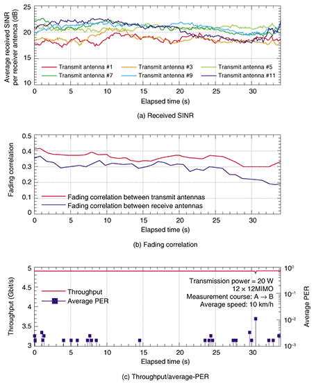
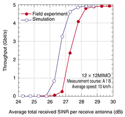
The time variations in the average total received SINR per receive antenna, the measured fading correlations between adjacent transmit antennas, and the average packet error rate (PER) along with the measured throughput using 12 × 12 MIMO multiplexing are shown in Fig. 4. Figures 4(a) and (b) reveal that the received SINR per transmit antenna fluctuated in the range from approximately 18 to 22 dB and that the variation in the measured fading correlation over the course was small: in the range of approximately 0.2 to 0.4. Figure 4(c) clearly shows that 4.915-Gbit/s packet transmission with an average PER below 10–2 was achieved at most of the locations along the measurement course, where the maximum distance from the base station was approximately 200 m. The measured throughput using 12 × 12 MIMO multiplexing as a function of the average total received SINR with a receive antenna spacing of 20 cm is shown in Fig. 5. The computer simulation results are also shown assuming a propagation channel condition corresponding to the average value of delay spread*37 and fading correlation between antennas along the measurement course in the field experiment. From the figure, we can see that the difference in the required received SINR between the results of the field experiment and those of simulation is less than 1 dB. The deviation is mainly due to the difference in the propagation channel model, channel estimation error, and signal detection error caused by quantization error in the A/D converter of the implemented MIMO receiver. Figure 5 also shows that peak throughput of 4.915 Gbit/s, i.e., frequency efficiency of approximately 50 bit/s/Hz, was achieved at an average total received SINR per receive antenna of approximately 28.5 dB when the receive antenna spacing was 20 cm by adopting the QRM-MLD signal detection method with ASESS.
5. ConclusionWe described the technology behind an ultrahigh-speed packet transmission field experiment using VSF-Spread OFDM radio access for achieving a maximum transmission data rate of approximately 5 Gbit/s with 100-MHz channel bandwidth and presented field experimental results. Using MIMO multiplexing consisting of 12 transmit/receive antennas in an actual outdoor propagation environment, we showed that ultrahigh-speed packet transmission with a maximum throughput of approximately 5 Gbit/s (spectral efficiency of approximately 50 bit/s/Hz) could be achieved with a required average total received SINR of approximately 28.5 dB. References
|
||||||||||||||||||||||||||||||||||||||||||||||||||||||||||||||||||||||||||||||||||||||||||||||||||||||