 |
|||||||||||||||||
|
|
|||||||||||||||||
|
Letters Vol. 6, No. 12, pp. 23–27, Dec. 2008. https://doi.org/10.53829/ntr200812le1 Application Area Expansion Technology for Optical Fiber Line Testing SystemAbstractThis article describes an optical fiber line testing system using a small-scale optical fiber selector for detecting water in cable joints in rural areas. We evaluated a prototype small-scale fiber selector. This system improves optical fiber cable network reliability and expands the application area of optical fiber line testing systems.
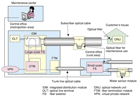
1. BackgroundThe number of fiber-to-the-home (FTTH) subscribers is increasing rapidly in Japan and exceeded 13 million in June 2008 [1]. Broadband optical access network provision currently requires each central office to accommodate thousands of optical fibers [2]. We have already developed an optical fiber line testing system that reduces construction and maintenance costs [3], [4]. A periodic test using an optical time domain reflectometer (OTDR) is an important aspect of maintenance work [5]. If water penetrates an underground closure over time, it can increase optical loss and degrade mechanical strength. Therefore, a water sensor module is attached to one fiber in an optical fiber cable in each underground closure for maintenance purposes. The broadband optical access network will expand into rural areas using optical fiber cables with fewer than 100 fibers. However, the conventional optical fiber selector (FS) is expensive for monitoring optical fiber cable in rural areas because it is designed to accommodate thousands of optical fibers. Moreover, the central office of a rural area is too small to accommodate a conventional testing system, so a worker must travel to this central office and measure the optical fiber cable when periodic tests are performed. However, rural central offices are usually a long distance from the maintenance center. This article describes technology for expanding the application area of the optical fiber line testing system. First, we introduce the configuration of our new testing system. Then, we report the optical characteristics of a prototype small-scale FS. Finally, we show the application area of our new testing system. 2. System configuration2.1 Testing systemOur new optical fiber line testing system with large- and small-scale FSs is shown in Fig. 1. The central office of a metropolitan area is equipped with an optical testing module (OTM) with an OTDR and a large-scale FS, which can select a target fiber from among thousands of optical fibers. Optical fiber lines must be tested to assess whether service demand, cable removal, and maintenance work have been performed correctly. An optical fiber line testing system performs various types of optical test remotely and can therefore reduce the operation time and cost. The functions of this optical fiber line testing system are listed in Table 1. In addition to testing for construction work, this system can perform various tests related to service demand, cable removal, and maintenance work such as fault isolation, fault location and periodic tests.
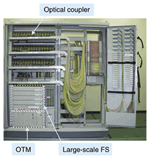
An operator in a maintenance center orders the OTM to perform various tests via a virtual private network. Next, the OTM retrieves optical fiber information from a database server. Then, the OTM measures the target optical fiber and returns the test results to the control terminal. The OTM is installed in an integrated distribution module, as shown in Fig. 2. It contains various types of optical measurement equipment such as an OTDR, an identification light source, and a power meter. The large-scale FS selects the target fiber, and an optical coupler introduces the test light into the target fiber.
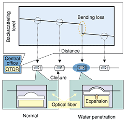
An optical filter is installed before the optical network unit (ONU) at each customer's house. This filter reflects the test light from the OTM and prevents its forward transmission but allows the communication light from the optical line terminal (OLT) to pass. Therefore, this system carries out automatic measurements, reveals fiber characteristics, and isolates and locates faults with no degradation in transmission quality. NTT has chosen to use the 1650-nm window for maintenance purposes in accordance with ITU-T Recommendation L.41 [6]. Each central office in a rural area is equipped with a small-scale FS and accommodates a few fibers for monitoring water penetration. The small-scale FS is controlled by the OTM via a VPN. The test light of the OTM passes through the trunk line optical cable, and the small-scale FS selects the target fiber to monitor water penetration. 2.2 Water sensor moduleThe water sensor module and its detection mechanism are shown in Fig. 3. If water penetrates an underground closure, an absorbent material in the sensor module expands and applies a bending force to the optical fiber. For the absorbent material, polyacrylic acid was chosen because its performance and long-term reliability have been determined [7]. The bending force induces bending loss, which can be detected by an OTDR. Moreover, the OTDR can determine the distance at which the bending loss is occurring, so it is possible to identify which closure has the problem. Therefore, water penetration in each underground closure can be monitored by performing periodic tests with the optical fiber line testing system.
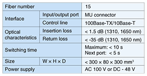
3. Small-scale FS3.1 SpecificationsWe clarified the specifications of a small-scale FS for rural areas, as listed in Table 2. The number of fibers is 15 because field data showed that central offices in rural areas accommodate fewer than 15 optical cables. The input and output optical ports use MU connectors because they provide high density and compactness. The control line is 100Base-TX/10Base-T for local area networks. The insertion and return losses are less than 1.5 and -35 dB, respectively, and these values are the same as those of an optical connector. The maximum switching time is less than 10 s to achieve short testing times. The target size is less than 300 mm × 80 mm × 300 mm for compactness. The power supply is –48 VDC or 100 VAC for use in Japanese central offices.
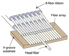
3.2 ConfigurationWe are developing a small-scale FS. The basic configuration of its switching part is shown in Fig. 4. It consists of a movable head fiber and a multifiber array, which is made by fixing bare multifibers onto a V-groove substrate with a pitch of 127 µm. The end of the multifiber array is cut with a perfect mirror end and aligned with the head fiber, which is positioned in the V-groove but does not touch the array. The switching part is placed in reflective-index-matching oil to improve the insertion and return losses. The movable fiber head can be moved vertically and horizontally to align it with the target fiber in the multifiber array.
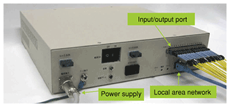
3.3 EvaluationWe evaluated the prototype small-scale FS. A photograph of it is shown in Fig. 5. The size is 300 mm (W) × 70 mm (H) × 270 mm (D). The insertion and return losses are less than 0.7 and -45 dB, respectively, at a wavelength of 1310 nm. We also performed a reliability test consisting of 100,000 switching cycles. The insertion and return losses were the same before and after switching. These results show that the prototype small-scale FS meets our requirements.
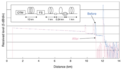
We also evaluated the prototype testing system with the small-scale FS before and after water penetration. The measured OTDR traces before and after water penetration are shown in Fig. 6. The wavelength of the test light was 1650 nm and the pulse width was 1 µs. From Fig. 6, we were able to locate the water penetration at a distance of 11.2 km.
4. ConclusionWe described an optical fiber line testing system that uses a small-scale FS to detect water in cable joints in rural areas. We evaluated a prototype small-scale FS. This system improves optical fiber cable network reliability and expands the application area of optical fiber line testing systems. References
|
|||||||||||||||||


