 |
|||||||
|
|
|||||||
|
Special Feature: NTT Tsukuba Forum 2008 Workshop Lecture 3 Vol. 7, No. 6, pp. 19–24, June 2009. https://doi.org/10.53829/ntr200906sf3  Next-generation Optical Fiber Cable System Technology for FTTH Expansion PeriodAbstractThe Access Media Project is researching new technologies for optical access network systems to support the next generation of fiber to the home (FTTH) scheduled to start after the optical mass deployment period, which will continue until 2010. This article describes the optical fiber technologies being studied in this R&D project, discusses the environment surrounding this technology and associated issues, and introduces next-generation optical fiber cable technology. It is based on a presentation given at the Tsukuba Forum 2008 Workshop held on October 16, 2008.
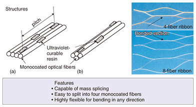
1. IntroductionThe Access Media Project is researching and developing optical fiber technologies that will play important roles in constructing and maintaining optical access networks. Consisting of four groups, it is divided horizontally into fundamental technology and application technology and vertically into optical cables/facilities technologies and maintenance technologies for each group’s target area. Trends in optical fiber technology are continually changing and it is important to keep one step ahead. There are currently three main issues that must be considered for the future. These concern manpower, facilities, and costs. If the reduction in the number of field workers continues at its present pace, there will be nearly 60% fewer workers in ten years than in March 2007. Furthermore, the average age of personnel is also expected to continue rising. Although the use of fiber to the home (FTTH) is certainly expanding, we are currently at a stage in which optical fiber must coexist with many metallic circuits. The complete migration of all of these metallic circuits to optical fiber will require the installation of about 30 million kilometers of new optical cable. With FTTH deployment being strongly promoted, installation costs now account for most FTTH-related costs, but operating costs are expected to increase with the FTTH penetration rate. 2. Technical issues for our R&D toward 20 million optical usersWe are currently at a stage where the R&D preparation for achieving NTT’s short-term objective of 20 million optical users by 2010 is nearly complete. We are therefore turning our attention to optical media technology R&D to deal with future issues, namely the maintenance and operation of a huge number of optical facilities, and to support a full-scale optical age. Our aim is to achieve a level of communications network quality equal to or better than that of the metallic network, in other words a level befitting the unique features of optical communications. To this end, we plan to replace conventional single-mode fiber (SMF) with hole-assisted fiber (HAF), which is more insensitive to bending loss, and to pursue our work based on the three pillars of (1) a new optical cable system, (2) a maintenance/operations system, and (3) a grand design. 3. Seeking the ultimate optical fiber cable system3.1 Optical fiber ribbon technologyWe are now developing novel optical-fiber ribbons and cables using bending-loss-insensitive optical fiber such as HAF. A schematic and a photograph of a novel optical fiber ribbon that we call rollable optical fiber ribbon [1] are shown in Fig. 1. The ribbon is composed of four monocoated optical fibers that are arranged linearly. Two adjacent fibers are fixed together periodically with ultraviolet-light-cured adhesive in the longitudinal direction. This structure enables the optical fiber ribbon to be rolled up easily and accommodated very tightly in cables. The ribbons are also compatible with mass fusion splicers and multiple-fiber connectors (e.g., MT connectors) in the same way as conventional optical fiber ribbons. They have high flexibility for bending in any direction and good separation characteristics.
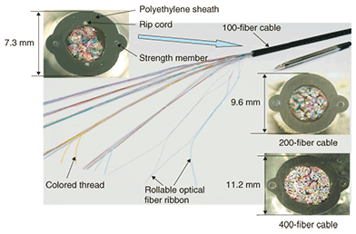
3.2 Optical fiber cable technologyConventional optical fiber cables were designed to suppress optical loss increases caused by the macrobending and microbending of the optical fibers inside the cable. However, the use of rollable optical fiber ribbons enables optical cables to have a more compact configuration because optical loss characteristics have little impact on cable design when bending-loss insensitive optical fibers such as HAF are used. In such a compact cable, optical fiber ribbons are bundled together in units of 20 or 40 fibers with a colored thread for identification, and the multiple units are incorporated into the cable without any other materials. We have already developed prototype optical fiber cables of this type for underground and premises use and have succeeded in reducing the outer diameter of the cable to the values given below (Fig. 2). –100-fiber cable (20-fiber unit × 5): cable outer diameter of 7.3 mm –200-fiber cable (20-fiber unit × 10): cable outer diameter of 9.6 mm –400-fiber cable (40-fiber unit × 10): cable outer diameter of 11.2 mm
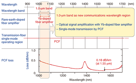
We have also been able to reduce the outer diameter of aerial optical fiber cables to 7.3 mm (100-fiber cable), which is about the diameter of an ordinary ball pen. The above cable diameter values are close to the calculated geometrical limits when we consider a simple square lattice for bundling optical fibers together very densely. In other words, cable cross-sections are being reduced to their ultimate values. Achieving ultrasmall-diameter, ultrahigh-density optical fiber cable will require monocoated optical fibers with a minimum bending radius of less than about 11 mm. (Here, we define the minimum allowable bending radius as that for which there is a loss increase of 0.2 dB per ten turns at a wavelength of 1.55 µm.) A conventional 1000-fiber slotted-type optical cable has an outer diameter of 23 mm and weighs 0.45 kg/m. In contrast, our ultrasmall-diameter, ultrahigh-density optical fiber cable with the same number of fibers has an outer diameter of 15.8 mm and weighs 0.19 kg/m. These values are 60% and 40% of those of the conventional cable, respectively, and closely approach the ultimate values. This technology has three benefits: (1) As an underground and premises facility, our cable can be installed in the vacant space in ducts that already contain cables, and it is suitable for lengthy installations. (2) As an aerial facility, it can be installed with low tension by the direct cable traction method, and it can be installed over long distances (installation distance: about twice that of conventional cables). (3) Moreover, in terms of resources, it uses less material overall than conventional cables, making for a more environmentally friendly facility. 3.3 Application to splitter and closure downsizingThe development of low-bending-loss optical fibers and cables is accelerating the design of optical splitters and closures that have a high housing efficiency. We are constructing a prototype optical splitter that uses optical fiber capable of withstanding an allowable bending radius of 15 mm (R15) or even tighter bending. This prototype is expected to have a housing efficiency 4.5 times that of existing optical splitter modules. As regards closures, until now it has been necessary to use a three-dimensional structure that satisfies an allowable bending radius of 30 mm (R30), which is the limit for SMF. If this limit can be exceeded by reducing the allowable bending radius, it will be sufficient to achieve a closure size that takes account of only workability. Specifically, it should be possible to achieve a 50% reduction in volume and a 25% improvement in working efficiency compared with existing closures. Our technology is being applied not only to free-bending optical cords (more than one million of these cords have been shipped to users) but also to jumper cords used within congestion-susceptible NTT offices as a preemptive measure against accidents. 3.4 Optical fiber connection characteristicsThere are two methods of connecting HAF: fusion splicing and mechanical splicing. In both cases, we have shown that connection loss can be kept to levels equivalent to that of SMF. Nevertheless, in addition to these two methods, we are also investigating a new connection technology based on adhesion. Adhesion-based connections should be particularly effective for holey optical fiber such as HAF and photonic crystal fiber (PCF) because they can maintain the holes. 3.5 Optical fiber technologyIn conventional optical-fiber structural design, a reduction in bending loss also causes a reduction in mode field diameter. In response to this problem, we studied HAF that can reduce bending loss while maintaining a mode field diameter comparable to that of SMF by enhancing the light-trapping effect. After producing a series of prototypes, we are close to a final design, and we have already confirmed that reliable operation can be achieved at small bending radii of 2.5–5.0 mm. 3.6 Optical fiber identification techniqueThe existing technique for identifying fibers during optical fiber installation and maintenance work in the field is to transmit a test light and detect light leaking from a bent section of the optical fiber. However, it is difficult to leak light from bending-insensitive optical fiber, so fibers cannot be identified using the existing technique. We have therefore developed a technique for extracting light by using a new optical fiber ID tester that uses a diffraction grating. This tester has an externally attached plate with precise ruggedness that creates a grating when it applies a load to the optical fiber under test. This grating produces leaky light for detection according to the grating period. By changing the grating design, we made the tester applicable to other kinds of optical fiber in addition to HAF, such as SMF. We are also trying to develop a fiber identification technique using birefringence. 4. Optical line switching without service interruptionWe are researching and developing technology for switching optical lines without interrupting services so that communication services never need to be suspended during network-related construction work. Although fast switching technology is in practical use, it cannot avoid momentarily breaking the link between an optical line terminal and an optical network unit. In an experiment we performed on a Gigabit Ethernet passive optical network (GE-PON) system in which the duration of the forced interruption was varied from 100 ns to 1 ms, we confirmed that the link was broken for about 6 s regardless of the interruption duration. We also found that the link restoration time became longer as the number of optical network units increased. We are therefore proposing a new switching technique that uses a detour line to replace a regular optical line with a new line. Our technique features the duplication of optical lines whose lengths must be adjusted. We have found from experiments that a difference of less than ±8 cm between the line lengths results in no broken GE-PON link. Therefore, staying within this range is a major premise of this technique. The procedure consists of five steps. First, connect a detour line beside the regular line and adjust the detour line length to within ±8 cm of the regular line length. Second, disconnect the regular line. Third, extend the length of the detour line by only the amount required for the replacement. Fourth, connect the new line, whose length is within ±8 cm of the detour line length. Fifth, disconnect the detour line. However, optical line duplication requires a change in the configuration of outside plant splitters from 1 × 8 to 2 × 8. Moreover, it requires technology that can adjust the optical line length to within ±8 cm without disrupting the optical link and technology that can measure optical-line length differences from the interference between duplicated optical pulses. We are now investigating such technologies and have already achieved successful experimental results. 5. Application technology for metropolitan and core networksWe continue to research and develop PCF as an optical fiber that can be applied to next-generation broadband transmission. Given the broadband single-mode transmission characteristics of PCF, we are investigating the 1.0-µm band as a new PCF-based single-mode wavelength region (Fig. 3) [2].
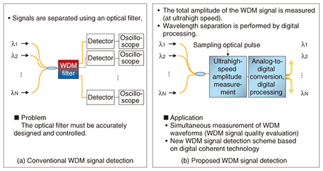
The main reason for selecting the 1.0-µm band is that it coincides with the region where light can be amplified by an ytterbium-doped fiber amplifier (YFDA), which means that we can achieve long-distance transmission equivalent to that of the existing 1.26- to 1.6-µm transmission wavelength regions. In other words, while SMF can transmit only in wavelength regions above 1.26 µm and has never been able to use the 1.0-µm band, a YDFA with PCF, which has broadband characteristics, enables high-speed signal transmission over a broad range of wavelengths from 1.0 to 1.6 µm. In addition, we are researching technology for generating pulse signals using wavelength division multiplexing (WDM). Here, we use a nonlinear optical fiber to expand the optical pulse spectrum (supercontinuum generation) and then use an arrayed waveguide grating to slice the signal and adjust its intensity, thereby simultaneously generating a WDM pulse signal. 6. Optical measurement technologyWe are developing a novel technology for WDM signal detection by using ultrafast optical sampling. In conventional technologies, an optical filter is used to distinguish each WDM signal, which is then detected by a photodetector and observed by an oscilloscope. This scheme requires accurately designed and controlled optical filters. In contrast, with our new approach, the total amplitude of the multiplexed signal is detected without optical filters, and then each WDM signal is recovered by digital processing. A key feature of this method is that the signal can be detected without high-precision optical devices (Fig. 4). We have already successfully tested this technology experimentally for two wavelengths, and we plan to extend it to multiple wavelengths in the future.
References
ProfileCareer highlightsProject Manager, Access Media Project, NTT Access Network Service Systems Laboratories. Masatoshi Shimizu received the Dr. Eng. degree in 1994. He joined Ibaraki Electronic Communication Laboratory, Nippon Telegraph and Telephone Public Corporation (now NTT) in 1983. Thereafter, he engaged in the R&D of technologies for optical subscriber line components, switching, and operating systems. From 1999, he was in charge of Internet business development mainly using space information in the Broadband Business Department, NTT East, and was also a part-time board member of CyberMap Japan Corp., which provides Mapion. From 2003, he was General Manager of the Planning Department at NTT Service Integration Laboratories. He has held his present position since 2004. |
|||||||


