|
|||||||
|
|
|||||||
       |
Special Feature: NTT Group R&D for Reducing Environmental Load Vol. 7, No. 10, pp. 9–13, Oct. 2009. https://doi.org/10.53829/ntr200910sf2 Development of Higher-voltage Direct Current Power Feeding System for ICT EquipmentAbstractThis article describes the development of a higher-voltage (approximately 400 V) direct current power feeding system for information and communications technology (ICT) equipment. It has higher efficiency than conventional alternating current systems, which can reduce the system cost. High-efficiency power feeding systems are an effective way to reduce ICT power consumption as well as low-power-consumption ICT equipment such as routers and servers and high-efficiency cooling systems. 
1. IntroductionIn recent years, the data center market has grown rapidly, and energy saving has become an important issue in the field of information and communications technology (ICT). A forecast for the Japanese data center market, power consumption, and floor space is shown in Fig. 1. Each item is expected to increase every fiscal year; in particular, the power consumption for fiscal year 2012 exceeds 10 billion kWh. Increasing the efficiency of power feeding systems for ICT equipment, such as router and servers in data centers, will provide huge energy savings as well as reducing ICT equipment power consumption and increasing cooling system efficiency. The –48-V direct current (DC) power feeding systems (DC48V), which have been widely used in telecommunications systems, have higher efficiency than the alternating current (AC) systems generally used in data centers so far. Therefore, discussion on applying DC systems in data centers as well has started globally.
However, power consumption increases as the performance of ICT equipment improves. The power consumption trend of ICT equipment is shown in Fig. 2. The power consumption of a one-rack-unit (1U) calculation server more than quadrupled between 2000 and 2006. As a result, larger-diameter power cables are needed to handle the large load current if DC48V systems are used, which causes construction and cable space problems. High-voltage direct current (HVDC) systems are expected to solve these problems.
2. Advantages of HVDCThe advantages HVDC are shown in Fig. 3. In general, ICT equipment components, such as central processing units, memory, and hard disks, operate on DC voltages of 3.3 or 5.0 V or sometimes 12 or 15 V. Therefore, it is necessary to convert the AC voltage supplied from the mains grid into the DC voltage used in data centers and communication buildings. Moreover, batteries that operate on DC voltage have to be connected for backup power. In the case of an AC power system, both AC-to-DC (AC/DC) and DC-to-AC (DC/AC) conversions are necessary to connect the batteries in uninterruptible power systems. AC/DC and DC/AC conversions are also necessary in ICT equipment to supply suitable DC power to the equipment’s components. As a result, there are four power conversion stages in an AC system. A DC power system, on the other hand, has only two power conversion stages because power from the rectifier and from the batteries can be supplied directly to the ICT equipment. In general, the power loss in each conversion stage is about 10% of the total converted power. Therefore, a DC power feeding system is fundamentally more efficient than an AC system due to the smaller number of power conversion stages. Furthermore, if the DC voltage is increased from the conventional –48 V to 400 V, the supply current can be reduced. This improves system cost and construction flexibility because smaller-diameter power cables can be used. An example of the power consumption breakdown in an AC power-fed data center is shown in Fig. 4. If the AC power feeding system were replaced by an HVDC one, the HVDC system could have fewer conversion stages, have lower conversion-stage loss, and use less power for the ICT equipment cooling and power feeding systems. The total reduction in power consumption is estimated to be about 15%.
3. HVDC development in NTT3.1 System configuration and development issuesAn HVDC power feeding system is being developed through a collaboration between NTT Energy and Environment Laboratories and NTT Facilities. The configuration and development issues are shown in Fig. 5. The basic configuration is the same as for conventional DC48V systems, for which we have a lot of experimental and practical data. Efficient development can be achieved by solving the new problems raised by changing the power feeding voltage from –48 to 400 V. The HVDC system is composed of a rectifier, batteries, and a power distribution cabinet (PDC). The rectifier usually rectifies the AC power to DC400V and supplies the power to the batteries and the PDC. The batteries back up the load power, and the PDC distributes the power to each piece of ICT equipment. Capacitors installed in the PDC suppress voltage fluctuations and prevent voltage oscillation in the system. In the case of a power line short-circuit resulting from ICT equipment breakdown, a fuse installed in the PDC blows, which immediately switches off the equipment and minimizes the effect on other ICT equipment. If the grid power fails, the batteries supply power without any intermittent discontinuity as a backup for the load power. The development issues involved in achieving higher-voltage power feeding are related to a higher-output-voltage rectifier, higher-voltage PDC, and optimized power feeding design, including greater user safety.
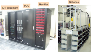
3.2 RectifierWe developed the first prototype in December 2008 and started to evaluate the system. A photograph of the system’s external appearance is shown in Fig. 6 and the specifications of the prototype rectifier are shown in Table 1. The system components, such as rectifier, PDC, and ICT equipment, are mounted on 2-m-high, 19-inch racks. The batteries are installed in another room. The prototype rectifier that NTT Facilities is in charge of developing provides a rated power output of 100 kW through a redundant configuration with nine (8+1) units, each with a rated power of 13 kW. The rectifier can be operated by changing the number of loaded or working rectifier units in accordance with increases and decreases in the power consumed by the ICT equipment by determining the optimum number of units when the units are operating near their rated outputs. This means that a decrease in efficiency caused by a partial load can be reduced. Moreover, if one of the rectifier units breaks down, we can replace only that unit without interrupting the power feeding operation; therefore, the reliability is extremely high. The output voltage is set to 401.4 V, and it can be adjusted to about 360 V. Measured rectifier conversion efficiency reaches 95% for output power of 80 kW. In the future, we will try to improve the conversion efficiency further by optimizing the conversion circuit itself. For the prototype system, we assumed that a load of 100 kW is provided as backup for 30 minutes or more. For this purpose, it has 180 lead-acid battery cells (200 Ah) connected in series.
3.3 PDCThe PDC contains fuses that are installed for every ICT load line, capacitor, and output connection terminal. It is necessary to optimize the circuit conditions, such as power cable lengths and diameters, ICT equipment input capacitance, and PDC impedances, to achieve a high-reliability power feeding system. We evaluated it through not only experiments but also computer simulations [1]. The equivalent circuit is shown in Fig. 7, which shows the setup for studying a short-circuit failure caused by ICT equipment. The rectifier, PDC, and cable impedances were modeled as the equivalent circuit, and SPICE (simulation program with integrated circuit emphasis) was used for the analysis. Simulated operating waveforms of the ICT equipment’s input voltage when the short-circuit switch was closed to imitate ICT equipment breakdowns are shown in Fig. 8. The input voltage of an unstable system decreased rapidly and dropped below half the power feeding voltage before failure occurred. Moreover, the voltage rapidly increased as resonant voltage was generated between the capacitance and the inductance in the system as a result of the fuse in the short-circuited ICT equipment blowing. For these cases, because the power feeding voltage deviated from the ICT equipment’s operational voltage range, equipment stoppages or breakdowns were forecast. To prevent such voltage fluctuations, it is effective to increase the ICT equipment’s capacitance or decrease the capacitor box’s impedance as much as possible. In the near future, we will optimize these conditions and try to achieve a highly efficient and reliable HVDC.
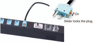
3.4 Electrical plugSince HVDC operates at a higher voltage than a conventional AC power feed, it is necessary to consider the safety of users. A safe connection method needed to be developed because an arc discharge is generated if the point of contact is cut off while electric current is flowing when a DC power feed is used. A plug developed by NTT Facilities for a DC400V power supply is shown in Fig. 9. This plug protects people from high voltage and from arc discharges. It has a mechanical lock (slider) to prevent the plug from being pulled out while power is being supplied, and power will not flow when this lock is off. These functions ensure safety without inconvenience.
4. ConclusionThe development background, advantages, and development status of an HVDC system were described. We aim to introduce the system into actual use after the final system prototype has been evaluated (by the end of fiscal year 2009) and after its practical use has been verified. Reference
|
||||||